Getting Started
v4.0.0
Which rescue switcher image is for your computer, how to install or upgrade it, and how to start it.
Which image
There is one image for each kind of computer:
| Computer | ROM size | Image |
|---|---|---|
| Atari ST, Mega ST | 192 KB | RESCUE_SWITCHER_v4.0.0_192KB.img |
| Atari STE, Mega STE | 256 KB | RESCUE_SWITCHER_v4.0.0_256KB.img |
| Amiga 500, 500+, 600 and 2000 | 512 KB | RESCUE_SWITCHER_v4.0.0_512KB.img |
A new SidecarTridge TOS or Kickstart board already has the right one on its ROMEMUL drive, named in RESCUE.TXT. The images are also on the downloads page and on the project’s releases page.
The rescue switcher 4.0.0 works only with firmware v4.0.0, and the firmware v4.0.0 only with the rescue switcher 4.0.0. A board updated from firmware v3.1.0 still has the rescue switcher 3.1.0, which stops at a “not compatible” screen: replace it as described below.
Installing or upgrading it
- Connect the board to your computer: the
ROMEMULdrive opens. - Copy the image for your computer to the drive.
Open
RESCUE.TXTand write the image’s name in it, exactly as the file is called, for example:RESCUE_SWITCHER_v4.0.0_192KB.img- Delete the old
RESCUE_SWITCHER_v3.1.0_...image, if there is one, unless you want to keep it in your list. - Eject the drive. The board rebuilds its list with the new rescue image.
The TOS and Kickstart upgrade guides include these steps: Upgrading the SidecarTridge TOS, Upgrading the SidecarTridge Kickstart.
Starting it
The board starts its rescue image:
- with the RESCUE button held while the computer is switched on, released once it has started (TOS, Kickstart);
- with
RESCUE_TIMEOUT, on a computer with a RESET button (the Atari ST family; the Amiga 500, 500+, 600 and 2000 have none): switched on with RESET held for longer than the seconds set inCONFIG.TXT(TOS); - on its own, when the board cannot serve the default image.
Where the RESCUE cable plugs in
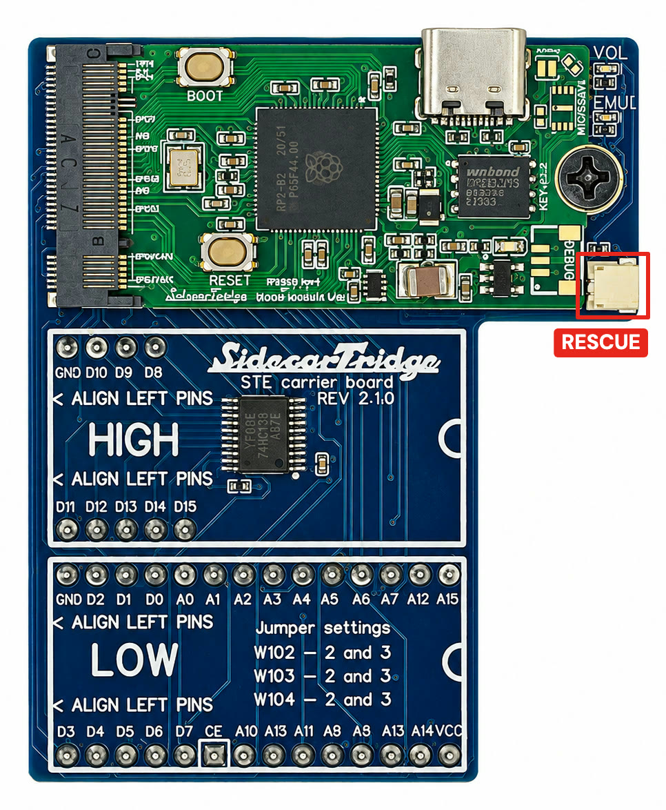
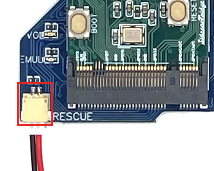
With board revision 4, the RESCUE cable plugs into a white two-pin connector on the carrier board.
On the TOS Emulator, the connector is at the right-hand end of the RP2M2 board, next to its DEBUG pads:
On the Kickstart Multi ROM, it is in the corner of the carrier board marked RESCUE, next to the VOL and EMUL LEDs:
With board revision 3, the RESCUE cable connects to pins on the back of the board. Its guides show where: TOS Emulator, Kickstart Multi ROM.
Once it has started, the User Guide explains its screens.