Getting Started
v2.1.0
This section provides guidance on the initial steps to start working with the SidecarTridge Multi-device board with the latest firmware v2. If you are a developer or maker it includes prerequisites, board assembly instructions, setup and configuration. Developers and Makers can also ensure a smooth start to their journey with the Multi-device board by following the procedures outlined in this and coming sections.
You can learn about the new features and improvements in the latest firmware release by watching the video below:
Table of contents
🚀 What’s new in Firmware v2?
Firmware v2 introduces a new architecture for the SidecarTridge Multi-device that brings flexibility, modularity, and a more efficient workflow — especially for power users and developers:
🧩 Modular Microfirmwares The core of v2 is the concept of Microfirmwares: standalone apps (ROM emulator, floppy emulator, RTC, custom tools, etc.) that you can install and switch between on the same hardware — no need to reflash the entire board.
📡 OTA (Over The Air) Downloads & Updates You can now browse and download Microfirmwares directly from official — and even private — Microfirmware repositories, over Wi-Fi. Install or update apps without removing the SD card or using a PC. A simple and secure way to keep your device up to date.
⚙️ Per-app Configurations Each Microfirmware stores its own settings in flash memory, isolated from other apps. This allows you to easily switch between functions without losing or reconfiguring settings.
🛰️ Offline-safe Manager + Atari terminal shortcuts Starting with Booster v2.1.0, the Manager stays usable even if Wi-Fi never connects: press
ESCon the Atari ST terminal to list the downloaded apps or holdSHIFTto keep booting from GEMDOS, and launch microfirmwares without the web UI.🛠️ Optimized Development Workflow & Architecture The v2 architecture separates the core firmware, global settings, and Microfirmwares — making the platform easier to extend and maintain. For developers, this enables a fast test cycle: build ST software on PC/Mac/Linux, test in an emulator, then copy to the device as a microfirmware. Expect faster innovation and more community-contributed Microfirmwares.
📶 Live signal + MAC telemetry The Manager screen and the shared web status banner show Wi-Fi signal strength (RSSI) and the Pico W MAC address, making it easier to debug weak networks or add the device to router allow-lists.
⬆️ Adaptive bus speed for Atari Falcon, TT and accelerated computers The new firmware can automatically adjust the bus speed to ensure compatibility with a wider range of Atari computers, including Falcon and TT models, as well as accelerated systems. This means improved performance and stability across different hardware configurations.
Prerequisites for All Users
Skills
To begin with the Multi-device board, all users are required to have a minimum experience with computers. Power on, power off, and basic knowledge of how to use a computer is enough to get started. However, it’s desirable for users to be familiar with the Atari 16/32 computer series, its hardware, and software.
Hardware
Users will need the following hardware:
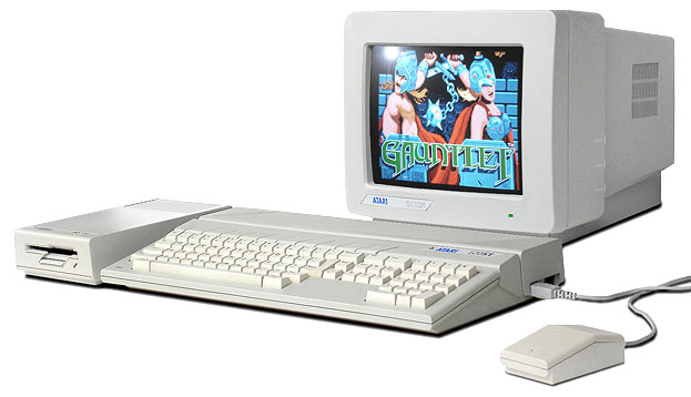
- An Atari 16/32 computer series: ST, STE, Mega ST, Mega STE, TT or Falcon. It’s worth noting that the Multi-device board can emulate a physical floppy drive, so an Atari 16/32 without a (or a broken) floppy drive can still be used with the Multi-device board.
- A Multi-device board
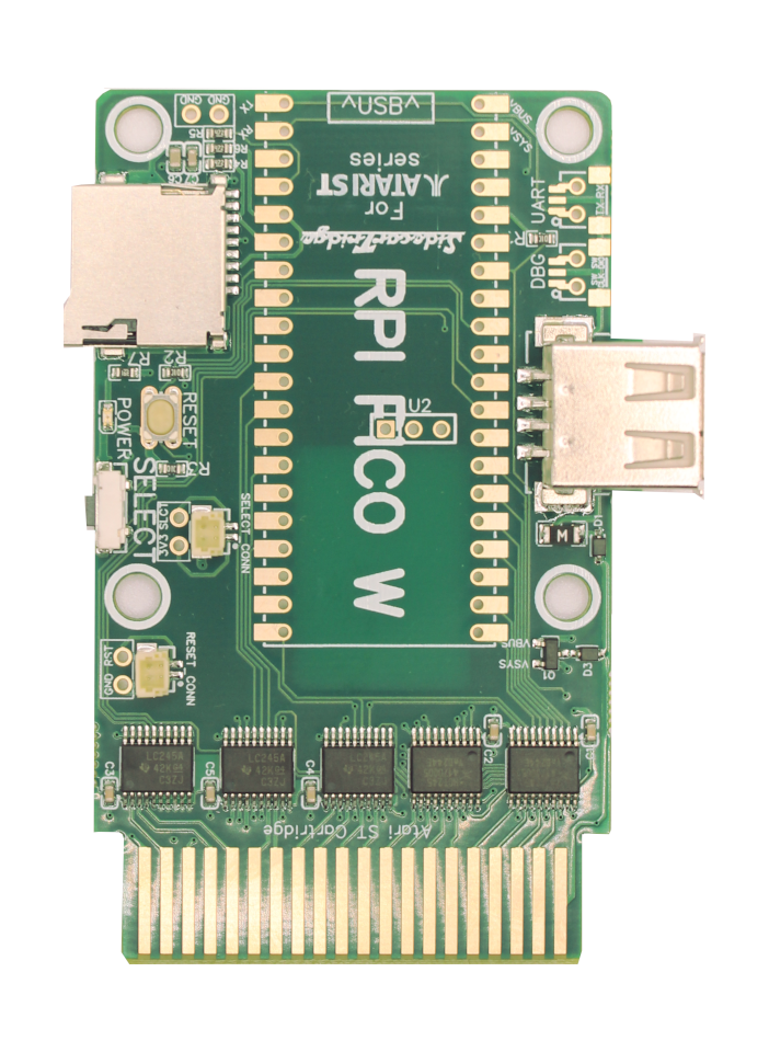
- A Raspberry Pi Pico WH (Reference SC0919), which already comes with the necessary 40-pin connectors to attach to the SidecarT’s motherboard, or a Raspberry Pi Pico W (Reference SC0918).
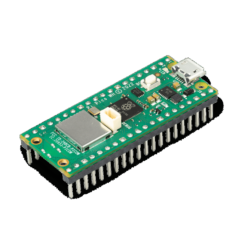
Since revision 3.1 of the board, the Raspberry Pi Pico W can be directly soldered to the board. If you want to use a Raspberry Pi Pico WH, you will have to solder two 20-pin female headers connectors to the board. You can find them in our store here, or in any electronic store.
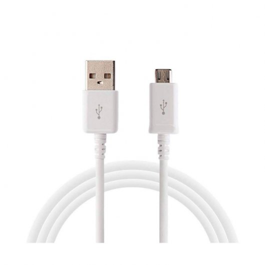
- A USB A to micro USB data cable to install and update the Multi-device firmware on the Raspberry Pi Pico W. It’s important to note the emphasis on a “data” cable - a simple charging cable won’t suffice.
- Since firmware version 2.0, a microSD card formatted as FAT32 or exFAT is required.
Initial Setup and Configuration
Firmware Installation
Starting in version v2.0.6Beta you don’t need to download the newer firmware version manually. Instead, the Booster app will report available updates and guide you through the installation process. The process described below applies to first time installation of the firmware or recovery process.
Option 1: Using the drag-and-drop method
- Connect the Raspberry Pi Pico W micro USB connector to your computer while holding the BOOTSEL button.
- Your computer should recognize the device as the mass storage device
RPI-RP2. Now you can release the BOOTSEL button. - Drag and drop the Full v2.1.0 Release file to the
RPI-RP2drive. - Wait for the file to be copied. When the copy is complete you can disconnect the Raspberry Pi Pico W from your computer.
Option 2: Using picotool
With this method you must first install the picotool helper tool, which is a command-line utility for managing Raspberry Pi devices based on the RP2040 microcontroller.
- Connect the Raspberry Pi Pico W micro USB connector to your computer while holding the BOOTSEL button.
- Your computer should recognize the device as the mass storage device
RPI-RP2. Now you can release the BOOTSEL button. - Flash the bootloader on your board:
picotool load -xv dist/rp-booster-$VERSION.uf2
Initial Factory Configuration
Format a microSD card with either exFAT or FAT32 file system and insert it into the SidecarTridge Multidevice board. We strongly recommend using a high-quality SDHC, SDXC or SDUC microSD from a reputable brand to ensure optimal performance and reliability. To format the microSD card, you can use the SD Card Formatter tool available for PC/Mac/Linux.
Plug the SidecarTridge Multidevice into the cartridge port of your Atari 16/32 series computer.
Power on the Atari 16/32 computer.
The Booster app will automatically start in Factory (Fabric) mode, the green LED of the Pico W on, and showing the following message on screen:
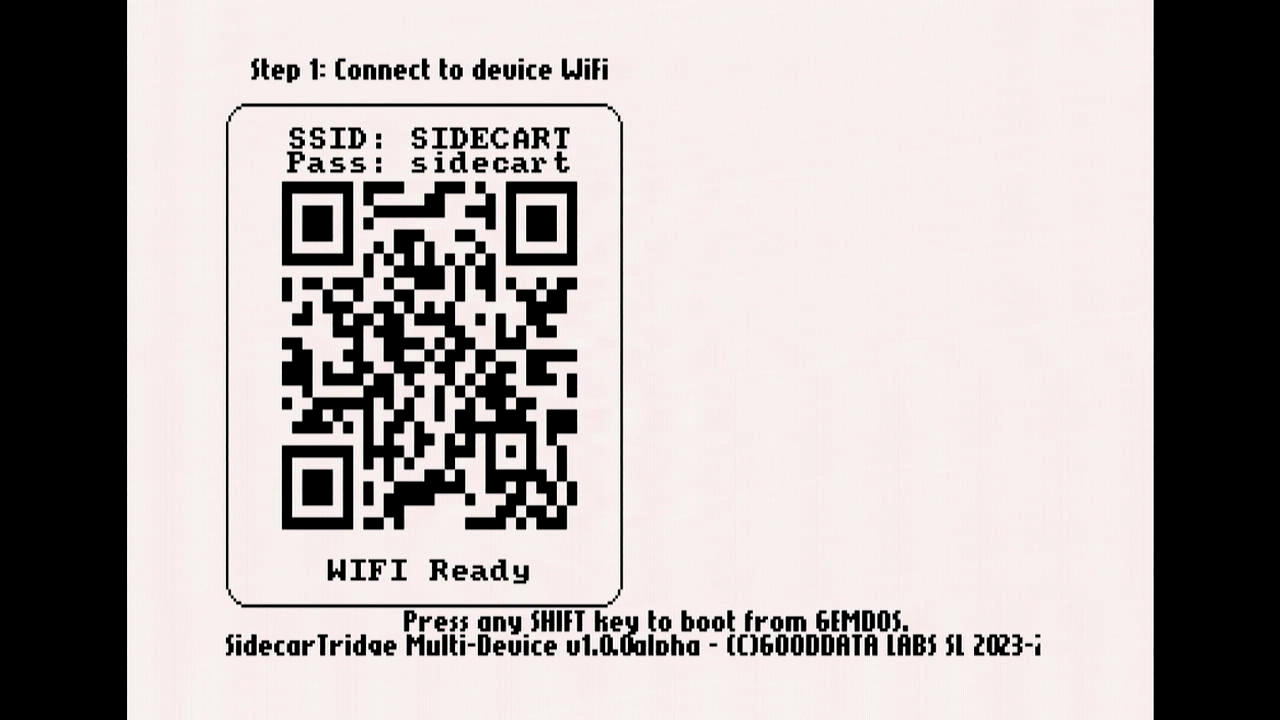
This screen confirms that the Booster app is running in Factory mode and is ready to be configured.
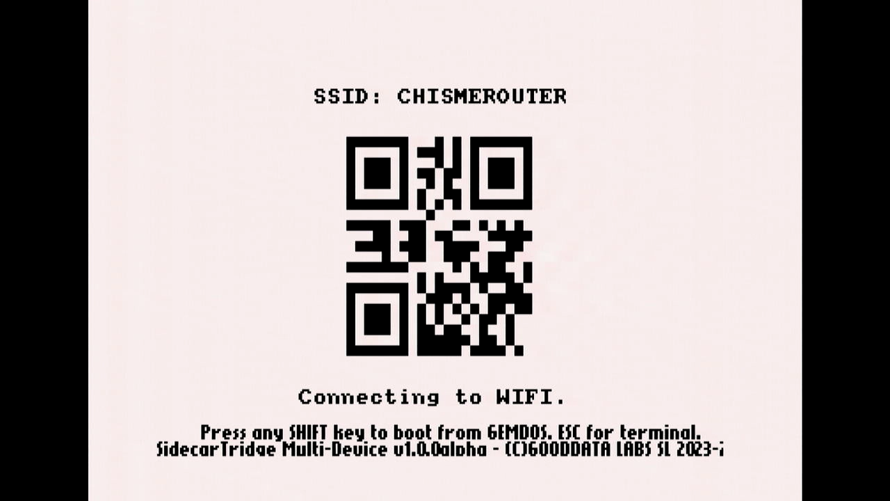
Scan the QR code with your smartphone to connect to the WiFi network created by the Booster app, or manually connect via your WiFi settings.
The default network details are:- SSID:
SIDECART - Password:
sidecart
- SSID:
Once connected to the WiFi, the Booster app will detect the connection and show the following screen:
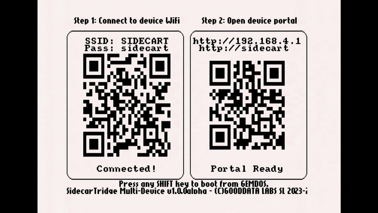
This screen invites you to open a web browser and navigate to either:
http://sidecart.local- or
http://192.168.4.1(if.localdomains aren’t supported)
In your web browser, enter the URL shown above to access the web interface.
You’ll be prompted to configure your home or office WiFi network.
Select your WiFi SSID from the list (you can click Refresh if it doesn’t appear), then click it to continue.
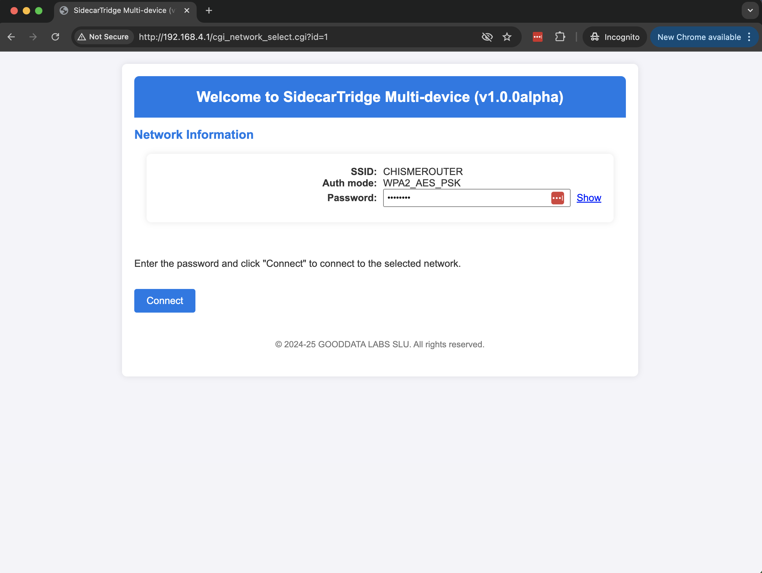
In this example, the network isCHISMEROUTER.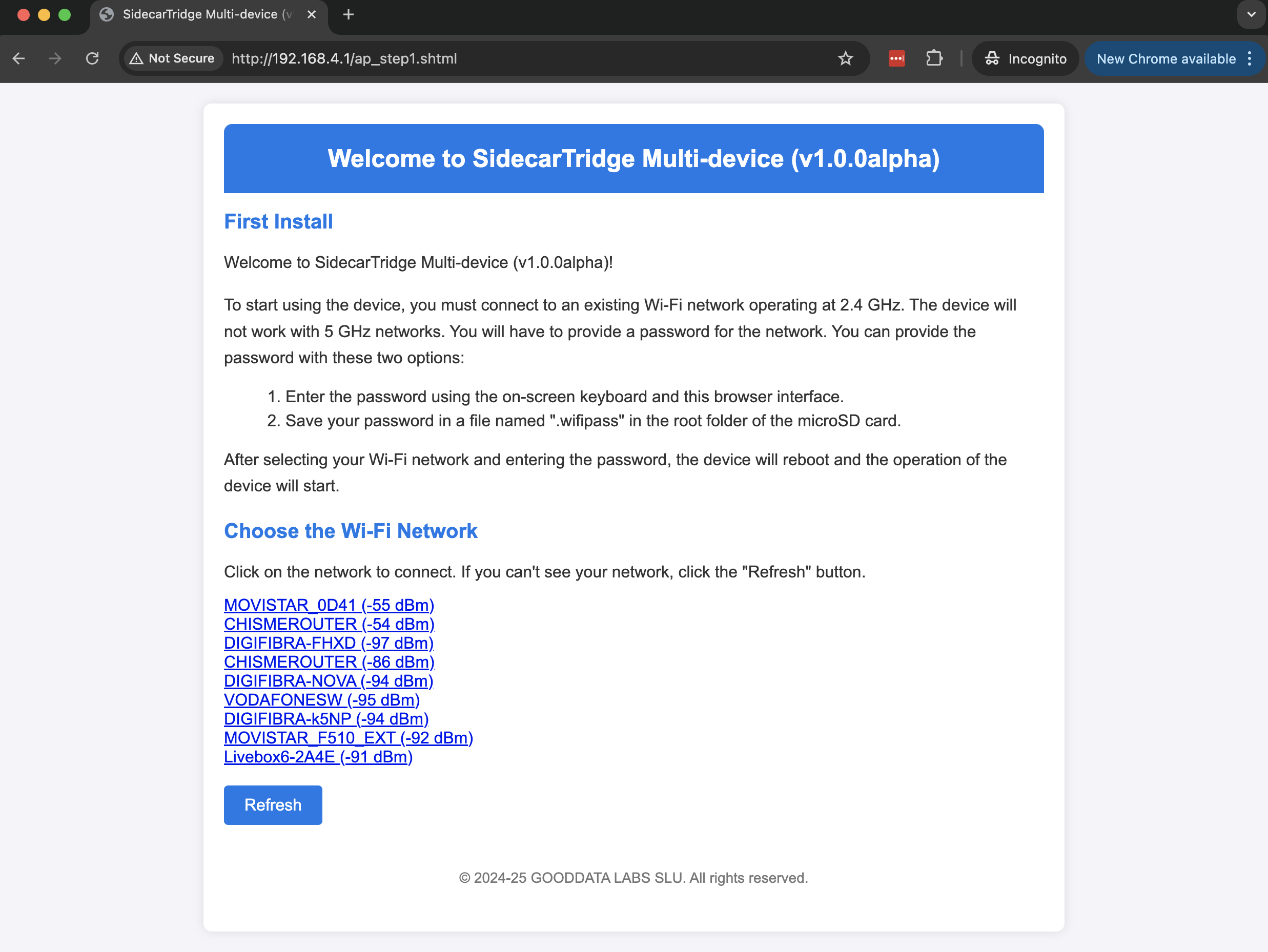
Enter your WiFi password and click the Connect button.
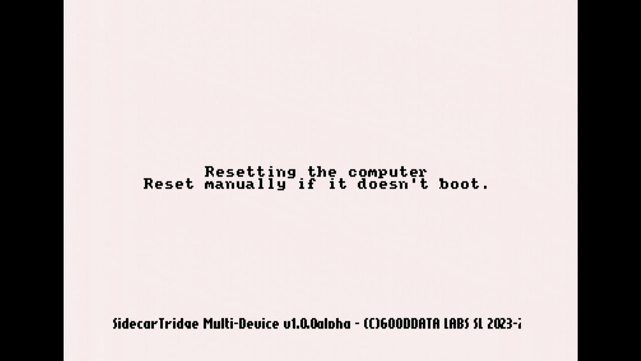
The Booster app will save the WiFi credentials to flash memory and reboot.
It will then connect to your WiFi network and show this message: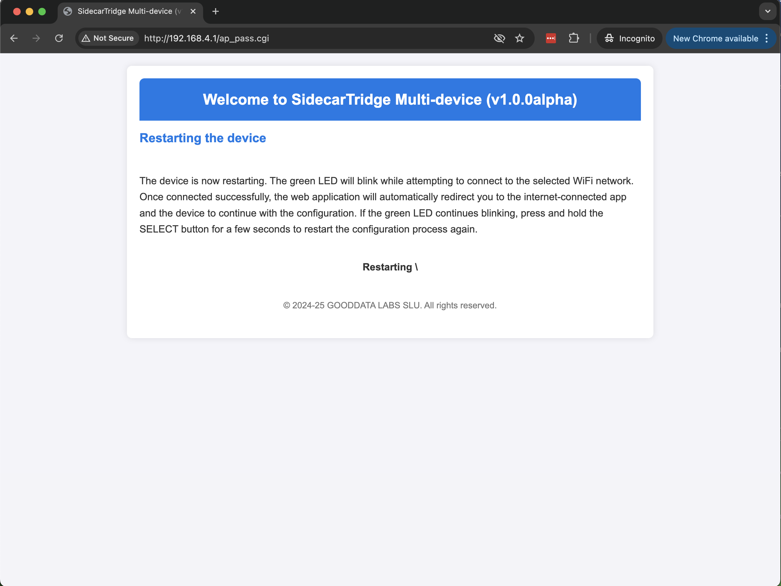
Meanwhile, the device will also display a reboot message on the Atari screen:
After rebooting, the Booster app will attempt to connect to your configured WiFi network:
Once connected successfully, the screen will show:
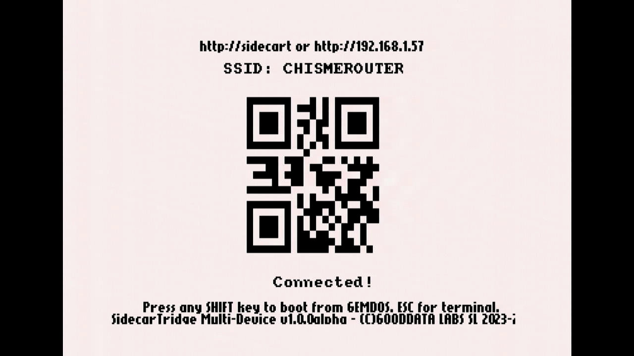
Your WiFi setup is now complete. From now on, the Booster app will boot directly into Manager mode.
Starting with Booster v2.1.0, even if Wi-Fi never connects you are no longer stranded: after the retry cycle the Atari ST terminal stays active so you can press
ESCto open the apps workflow or hold anySHIFTkey to keep booting from GEMDOS. From there you can launch the microfirmwares you already downloaded, entirely offline.If you later notice unstable connectivity, newer firmware versions can also show the signal strength directly on the Atari ST screen, without the need to enter Manager mode in the Booster app. You can also open the WiFi view and enable Show RSSI to display the RSSI value in dBm for visible WiFi networks. As a general reference, use the first matching threshold in the table below.
RSSI Value (dBm) Signal Strength Probability of Good Connectivity >= -30 dBmExcellent Very high >= -40 dBmVery good High >= -50 dBmGood Good >= -60 dBmOK Usually good >= -67 dBmMinimum for stable WiFi Acceptable >= -70 dBmWeak Borderline >= -80 dBmVery weak Low < -80 dBmAlmost unusable Very low Below
-80 dBm, the signal strength is considered weak and can lead to connectivity issues. The board may fail to connect to the selected WiFi network, lose the connection intermittently, or take longer to obtain an IP address from DHCP. Monitoring RSSI values helps you identify networks with stronger signals and connect to more reliable WiFi networks.
Now you can start using the Booster app to manage your microfirmware apps! Learn how to do it in the User Guide.
If the app fails to connect to your WiFi network (for example, due to an incorrect password), it is possible to revert to Factory mode by pressing and holding the SELECT button for more than 10 seconds while powering on the computer. Another option is to create a .wificonf file on the microSD card as described below in the Auto setup and headless factory configuration section. As a last resort, you can also reflash the firmware using the methods described above.
Auto setup and headless factory configuration
Starting with version 2.0.6 Beta, the Booster app supports an automatic setup mode that lets you configure WiFi without connecting to the Booster access point.
To use this feature, create a file named .wificonf in the root directory of the microSD card before inserting it into the Multi-device board. The file must contain the following entries:
SSID=YOUR_WIFI_SSID
PASS=YOUR_WIFI_PASSWORD
; AUTH values. Use numeric values only
; OPEN=0
; WPA_TKIP_PSK=1
; WPA2_AES_PSK=5
; WPA2_MIXED_PSK=8
AUTH=AUTH_VALUE
Replace YOUR_WIFI_SSID and YOUR_WIFI_PASSWORD with your actual network credentials. Set AUTH_VALUE to the numeric value that matches your WiFi authentication method, as listed in the comments above.
When the Multi-device board is powered on with this preconfigured microSD card, the Booster app will automatically read the .wificonf file, connect to the specified WiFi network, and skip the manual setup process.
This mode is especially useful for headless setups, such as when no display is available or input devices are not working.
Once the microSD card is inserted, connect the Multi-device board to a power source using a micro-USB cable. The Booster app will boot and connect to your WiFi network automatically. After a few seconds, you can access the Booster web interface at:
http://sidecart.local, orhttp://<your_device_ip_address>
If sidecart.local does not resolve, check your router’s connected devices list to find the IP address assigned to the Multi-device board.
Now you can start using the Booster app to manage your microfirmware apps! Learn how to do it in the User Guide. The Booster app operates independently of the Atari ST. You can power the Multi-device board without connecting it to the computer, which is ideal for headless operation or troubleshooting.
Prerequisites for Developers and Makers
Skills
To begin with the Multi-device board, developers are required to have a minimum experience with C. However, it’s desirable for developers to be proficient in C, 68000 Assembler, Microcontroller development, and have a deep understanding of Atari 16/32 peculiarities. To contribute effectively to the Multi-device project, having a foundation in certain skills will be beneficial. Here’s a breakdown:
C Programming: Essential for software development and firmware writing. Ensure you have a grasp on data structures, memory management, and algorithm development within C.
68000 Assembler: Crucial for understanding and working with low-level part of the firmware for Atari 16/32.
Microcontroller Development: Familiarity with microcontrollers, especially with Raspberry Pi Pico’s microcontroller RP2040, is vital. You should understand how to write, test, and debug firmware, manage I/O operations, and deal with real-time constraints.
Atari 16/32 Knowledge: A robust understanding of Atari 16/32 hardware and software, its system call and memory management will significantly boost your contribution efforts.
Version Control/Git: Ability to effectively use git, manage branches, resolve merge conflicts, and understand the workflow to keep the codebase stable and collaborative.
Testing and Debugging: Practical know-how on debugging, writing test cases, and validating hardware/software integration ensures a robust build.
Visual Studio Code Expertise: Familiarity with using Visual Studio Code, configuring workspaces, managing extensions, and utilizing its debugging capabilities will facilitate a smoother development experience.
GCC: Understanding how to utilize GCC for compiling C and C++ code, managing dependencies, and debugging is vital for software development in this project.
VASM: Knowledge of using the VASM assembler, its syntax, and how to compile assembly code, particularly for the 68000, will enable efficient low-level development.
Makefile: Know-how on writing and managing Makefiles to automate build processes, manage dependencies, and optimize the development workflow.
Integration with GDB: Skills in using GDB for debugging software, setting breakpoints, inspecting variables, and analyzing program flow, especially in conjunction with Visual Studio Code, are essential for troubleshooting and ensuring software stability.
And if you want to contribute to the harware, skills in reading schematics, understanding electronic components, and practical skills like soldering will facilitate working with the hardware aspects of Multi-device.
Even if you’re not an expert in all these areas, your contribution is still valuable. Engage, learn, and grow with the Multi-device community!
Hardware
Additionally, developers need the following hardware:
An Atari 16/32 computer series: ST, STE, Mega ST, Mega STE, Falcon or TT.
A Multi-device board (See above)
A Raspberry Pi Pico W or WH board to connect it to the Multi-device board. The
Wstands for Wireless and theHstands for Header. TheHversion comes with the header pins already soldered to the board and a JST debugger connector needed to connect the Raspberry Pi Debug Board. Since version 3.1 of the board, it’s also possible to get the debug signals directly on the JST connector of the board.
- A Raspberry Pi Debug board or an equivalent debug board to connect it to the Multi-device board
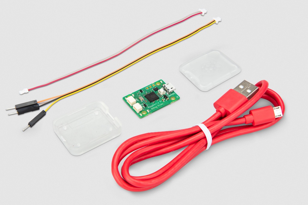
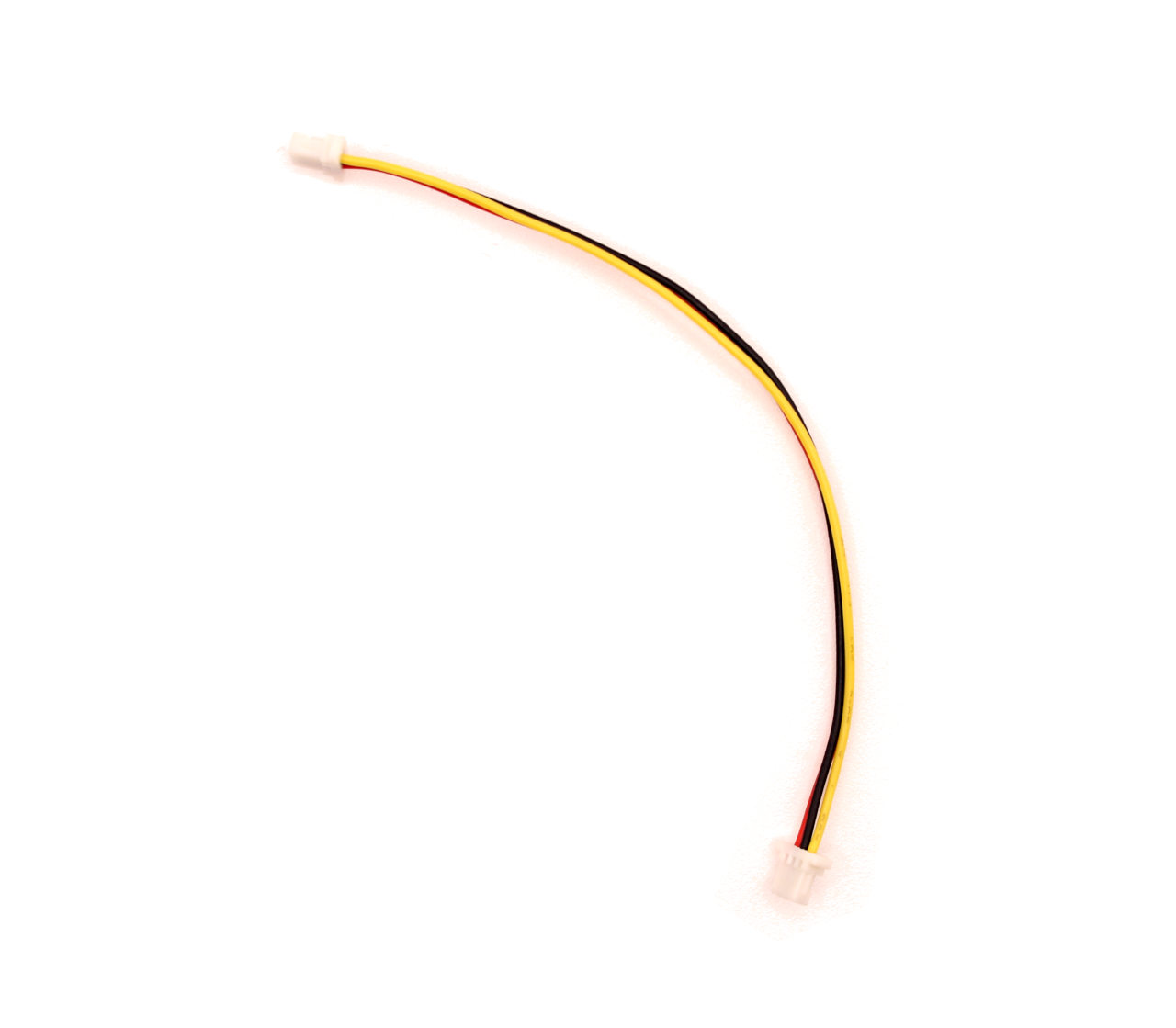
- A Mini JST SH 1.0mm pitch double 3xpin female connectors to connect the UART pins from the Raspberry Pi Pico W to the Raspberry Pi Debug board
- A Windows PC, Linux or a Mac with a USB port to connect to the Raspberry Pi Debug board and the Raspberry Pi Pico W board to program it
These prerequisites are considered as a minimum baseline. Being well-versed with the aforementioned technologies and having the required hardware will ensure a seamless initial experience with the Multi-device board.
Board Assembly
Anyone with the requisite skills can opt to build their own Multi-device board. The schematics needed to assemble the board can be found in the Github repository. It provides detailed blueprints to guide users through the assembly process.
However, it is worth noting that acquiring the board through our online shop is likely to be both cheaper and more convenient, given the complexities involved in assembling the board.
Assembling the board independently can be a rewarding and enriching learning experience for those who are interested in a hands-on approach to understanding the intricate workings of the Multi-device board. Obviously, it is not recommended for those who are new to hardware development.