Internal riser boards for Mega ST and Mega STE
These internal riser boards are installation add-ons for the ACSI2STM Compact model, designed specifically for the Atari Mega ST and Mega STE. They let you mount the Compact board inside the computer, keeping the setup tidy and avoiding an external device hanging from the rear ACSI port.
These riser boards are for the ACSI2STM Compact only. They require the rear IDC 20-pin connector (sometimes referred to as the “Satan Disk” connector), are not compatible with the ACSI2STM Mini, and compatibility with third-party ACSI2STM variants is not guaranteed.
What this add-on does
- moves the ACSI2STM Compact inside the case
- avoids an external box and external cabling on the back of the computer
- provides a cleaner installation for Mega ST and Mega STE builds
- powers the Compact internally through the included wiring/cable set
Two versions
There are two different riser boards because the internal layout of the Mega ST and Mega STE is not the same.
Mega ST riser board
This version is designed for the Atari Mega ST and includes the extra power wiring needed for that machine.
Kit contents:
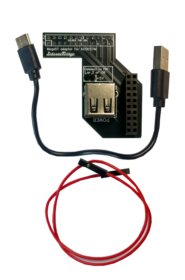
- Mega ST riser board
- pre-soldered 24-pin female connector
- pre-soldered IDC 20-pin female connector
- pre-soldered USB-A power connector
- two pre-soldered male pins for 5V power connection
- 20 cm female-to-female Dupont red connector
- USB-A to USB-C cable
Mega STE riser board
This version is designed for the Atari Mega STE and matches the internal connector layout of that machine.
Kit contents:
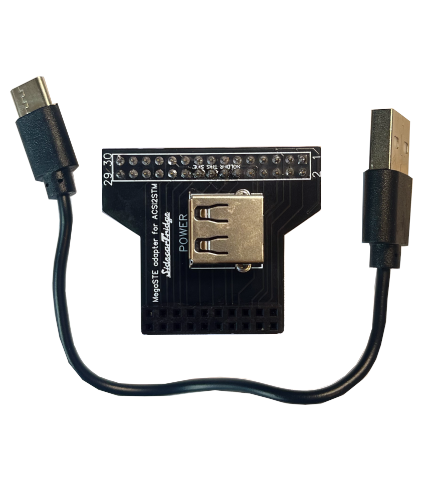
- Mega STE riser board
- pre-soldered 30-pin female connector
- pre-soldered IDC 20-pin female connector
- pre-soldered USB-A power connector
- USB-A to USB-C cable
Important compatibility note
To use these riser boards, your ACSI2STM Compact must expose the IDC 20-pin connector at the back of the board. All SidecarTridge-produced Compact boards were designed with this connector in mind, although depending on revision or kit option it may not always come pre-soldered.
If you are using a Compact board from another manufacturer, please verify the connector layout before buying the riser board.
Before you start
Before opening the computer, make sure that:
- you are using an ACSI2STM Compact
- your Compact has the rear IDC 20-pin connector required by the riser board
- you are comfortable opening the machine and checking cable routing inside the case
- the Atari is fully powered off and disconnected from mains power
Installation guide
The exact internal layout differs between the Mega ST and Mega STE, so treat the riser board as model-specific. The steps below are based on the available kit contents and the current product images.
Always power the Atari off completely and disconnect it from mains power before opening the case.
Installing the riser board in an Atari Mega ST
- Open the Mega ST case and locate the area where the ACSI2STM Compact will sit without interfering with the floppy drive, shielding, or airflow.
- Verify that your ACSI2STM Compact has the rear IDC 20-pin connector available for the riser board.
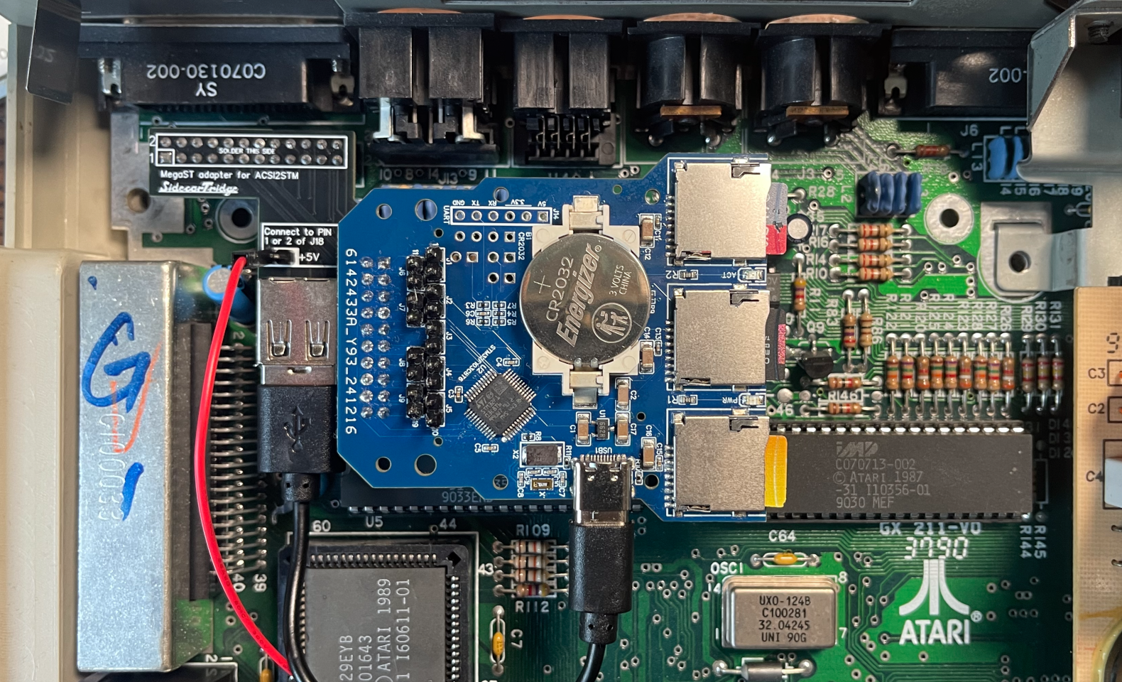
- Fit the Mega ST riser board in its intended internal position.
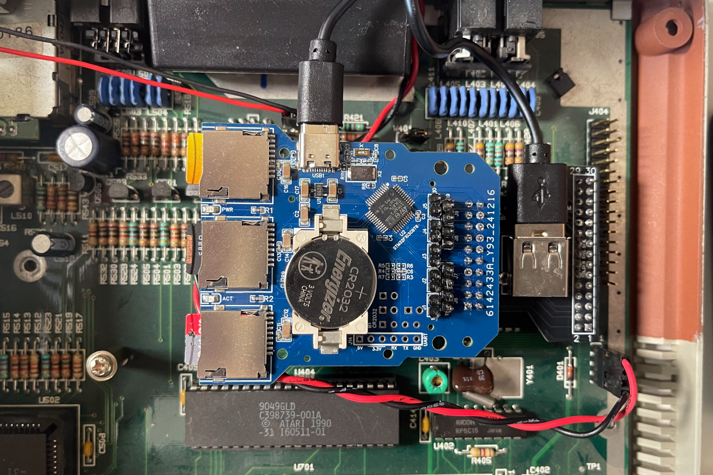
- Connect the Compact to the riser through the IDC 20-pin connector, making sure the board is fully seated and not under tension.
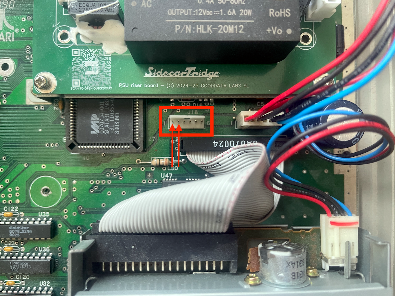
- Use the included 5V power pins and female-to-female Dupont cable to supply 5V power only from the Mega ST motherboard to the riser board. On the Mega ST motherboard, use pin 1 or pin 2 of connector J18, which both provide 5V. J18 is located between the power supply and the floppy drive, on the left side of the power supply connector. See the image below for reference.
- The red Dupont lead is the power lead included with the Mega ST kit. If you are not sure about the power connection, do not improvise with alternative points on the motherboard.
- Connect the included USB-A to USB-C cable from the riser board’s USB-A power connector to the USB-C power input on the ACSI2STM Compact.
- Double-check that the Compact, riser, and cables do not foul the keyboard frame, top cover, or any nearby metal shielding.
- Reassemble the machine and perform a first boot test before fully closing everything permanently.
Practical checks for Mega ST:
- the Compact should remain mechanically stable when the case is moved
- the USB-C lead should not be sharply bent
- the Dupont power lead should be routed away from sharp metal edges
Installing the riser board in an Atari Mega STE
- Open the Mega STE case and identify the internal mounting area for the ACSI2STM Compact.
- Verify that your ACSI2STM Compact exposes the rear IDC 20-pin connector required by the riser board.
- Fit the Mega STE riser board into place using the connector layout intended for the Mega STE chassis.
- Seat the Compact onto the riser through the IDC 20-pin connector, ensuring correct alignment and no lateral stress on the pins.
- Connect the included USB-A to USB-C cable from the riser board’s USB-A power connector to the Compact’s USB-C power input.
- Unlike the Mega ST version, the Mega STE kit does not use the extra Dupont power lead included with the Mega ST board.
- Check that the whole assembly clears the internal shielding and any nearby drive/cable routing.
- Reassemble the computer and test that the Compact powers correctly and is detected as expected.
Practical checks for Mega STE:
- confirm that the riser sits flat and the Compact is not twisted on the connector
- make sure the USB power cable does not get trapped by the lid or shielding
- verify that SD card access remains practical after installation
Troubleshooting after installation
If the installation does not work as expected, check the following first:
- The device is not detected: make sure the Compact is fully seated on the IDC 20-pin connector and that the riser is aligned correctly.
- The Compact does not power on: verify the USB-A to USB-C power link, and on Mega ST also re-check the 5V connection at J18.
- The lid does not close cleanly: inspect cable routing again and make sure no lead is trapped under shielding or pressed sharply against the case.
- Do not connect or disconnect internal connections while the system is powered on.
Before closing the case completely, it is a good idea to perform a partial test boot and confirm that the board sits flat, powers correctly, has no pinched cables, and that the Atari detects the storage device normally.