Hardware Installation
The different Atari ST models are encased in a plastic outer shell that must be fully removed to access the internal components. This guide will walk you through the steps necessary to open these cases and install the SidecarTridge TOS Emulator safely and effectively.
IMPORT INFORMATION ABOUT THE ATARI ST MODELS: The metal shielding inside the Atari ST models can be too tight and in some cases it must be removed to close the plastic case properly.
Table of contents
Opening the Atari ST Case
Overview
Once the plastic case is removed, you’ll find a metal shielding that also needs to be taken off to reach the ROMs and other crucial parts of the computer. The user must remove both the plastic and metal casings to access the internal components safely. This process requires a few tools and safety precautions to prevent damage to the Atari ST and ensure a successful installation of the SidecarTridge TOS Emulator.
Tools Required
- Phillips-head screwdriver
- Flat-head screwdriver (optional, for prying)
- Anti-static wrist strap (recommended)
Safety Precautions
- Power Off and Unplug: Ensure the Atari ST is powered off and unplugged from any power source before beginning the disassembly.
- Ground Yourself: Wear an anti-static wrist strap to prevent static electricity from damaging internal components. Alternatively, touch a grounded metal object periodically to discharge static electricity.
- Work on a Clean Surface: Use a clean, static-free workspace to prevent any debris or static discharge from interfering with the components.
Step-by-Step Instructions
- Remove the Screws of the plastic case:
- Turn the Atari ST upside down and locate the screws securing the case.
- Using a Phillips-head screwdriver, carefully remove all the screws. Keep the screws in a safe place for reassembly. There are plenty of YouTube videos showing how to open an Atari ST case.
- Separate the Case Halves:
- Once the screws are removed, gently separate the top and bottom halves of the case.
- If the case is difficult to open, use a flat-head screwdriver to carefully pry the halves apart, being mindful not to damage the plastic.
- Remove the Metal Shielding:
- After removing the plastic case, you’ll find a metal shielding covering the internal components.
- Locate the screws securing the metal shielding and remove them using a Phillips-head screwdriver.
- Also locate the secure tabs that hold the shielding in place and gently release them.
- Carefully lift the metal shielding off the Atari ST to access the internal components. It can be complicated to remove some parts of the metal shielding, especially around the power supply.
- Locate the Atari ST ROMs:
- Once the metal shielding is removed, you’ll find the Atari ST ROM chips.
- Depending on the Atari ST model, they will be in different locations:
Atari STF/STFM: The ROMs are located at the left side of the motherboard, under the power supply unit or below the keyboard. 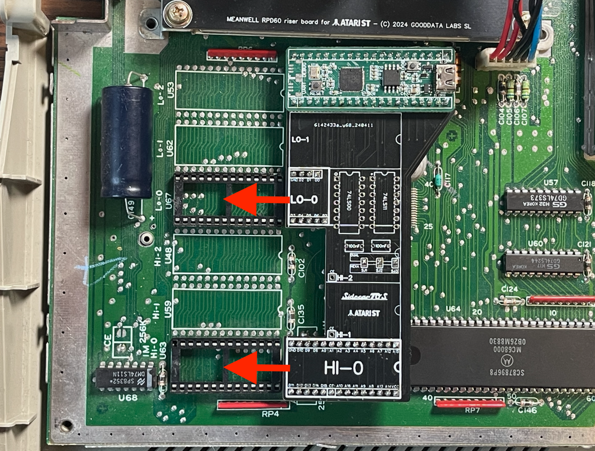
Atari STE: The ROMs are located near the keyboard connector, partially covered by the floppy drive. 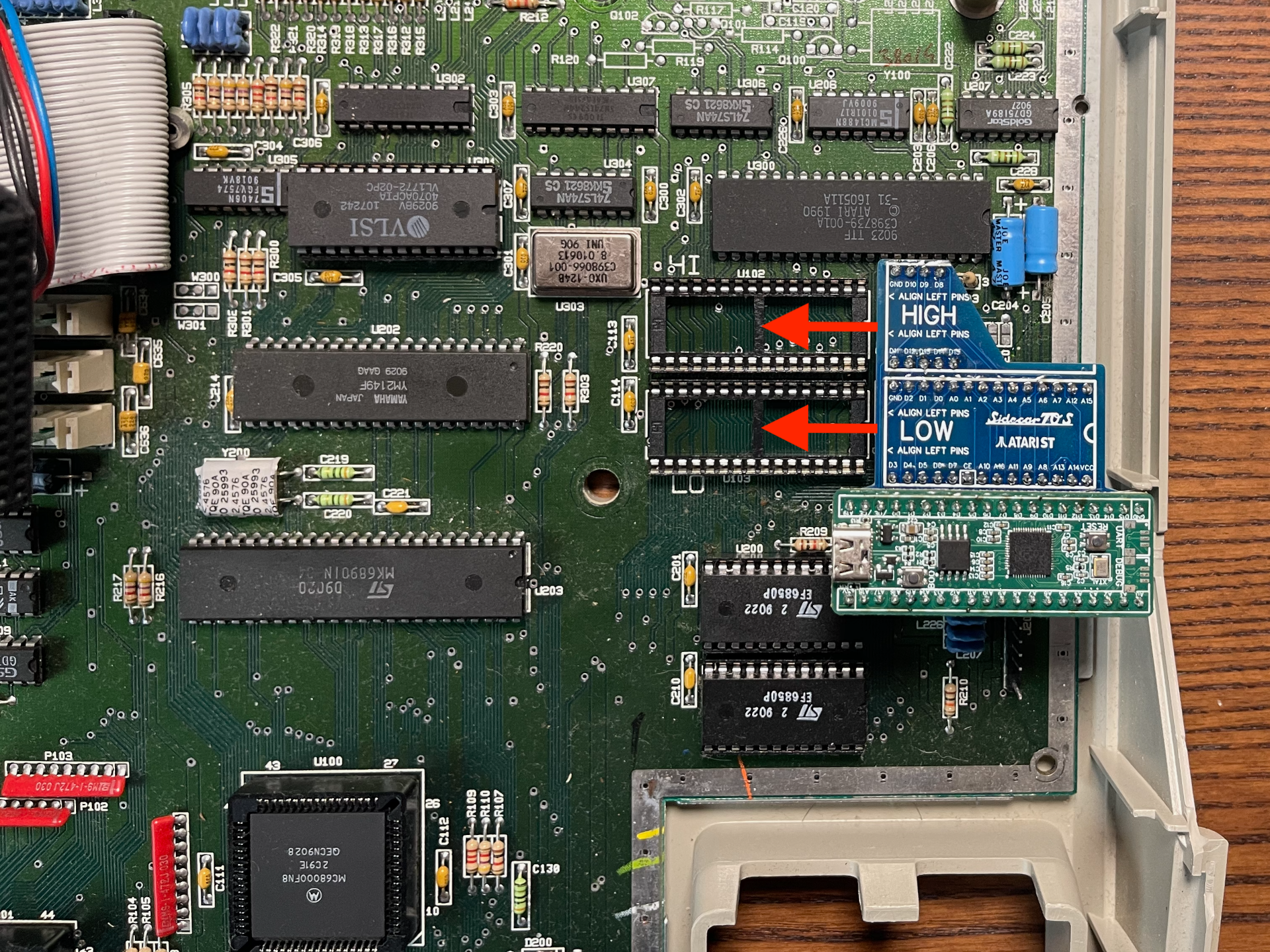
Atari Mega STE: The ROMs are located at the right side of the motherboard close to the bottom edge, below the hard disk drive unit. 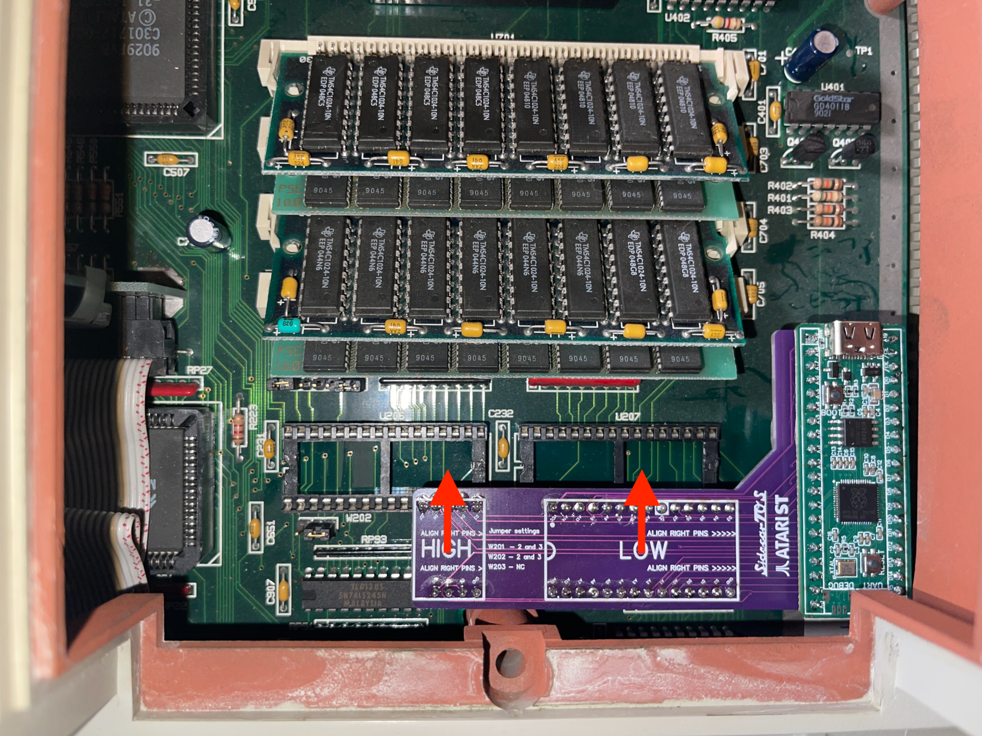
By following these instructions, you can safely open your Atari ST case and prepare for the hardware installation of the SidecarTridge TOS Emulator.
Unplugging the Atari ST ROMs
If the ROM chips are soldered to the motherboard, it is recommended to seek professional assistance to avoid damaging the Atari ST. This guide assumes the ROM chips are socketed and can be removed without soldering.
Use a Chip Extractor or Flat-Head Screwdriver
If you have a chip extractor tool, use it to carefully lift each ROM chip out of its socket. If you don’t have a chip extractor, use a flat-head screwdriver. Gently insert the tip under one end of the chip and slowly pry it upward. Repeat on the other end until the chip is free.
Be very careful to lift the chip evenly to avoid bending the pins. Also, avoid using excessive force, as this can damage the chip, the socket, or the motherboard.
Handle ROM Chips with Care
Once removed, place the ROM chips on an anti-static mat or in an anti-static bag to protect them from static damage.
Inspect the Sockets
Inspect the now-empty sockets on the motherboard for any debris or damage. Clean if necessary, using compressed air or a soft brush.
Jumper Settings on the Motherboard
The SidecarTridge TOS Emulator carrier board is configured to replace the original ROMs pin by pin. If the computer has jumpers to select the chip types, set them to match the original ROMs as follows:
Atari ST C070789 Motherboards
Dual ROMs
The jumpers must be set to the 1M position for all jumpers on a motherboard with only two ROMs (the original ROMs are 1Mbit).
- A17 jumper: 1M position
- A18 jumper: 1M position
- CE jumper: 1M position
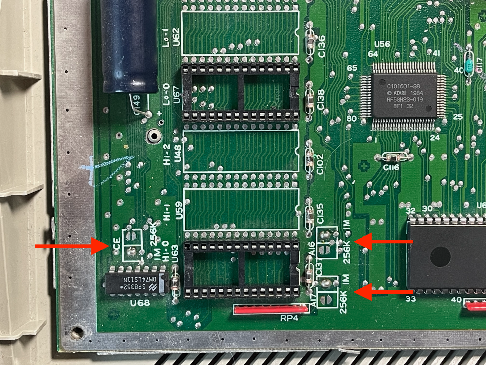
Six ROMs
The jumpers must be set to the 256K position for all jumpers on a motherboard with six ROMs (the original ROMs are 256Kbit).
Atari ST C070243 Motherboards
Six ROMs
This is the default configuration for this motherboard version. No changes are needed.
Dual ROMs
This configuration is quite unusual in this motherboard version. We assume that only modded computers have this configuration, so the user has already modified the board to support dual ROMs, a not so common modification.
Atari ST C070523 Motherboards
Six ROMs
This is the default configuration for this motherboard version. No changes are needed.
Dual ROMs
Not supported.
Atari Mega ST
Dual ROMs
Only dual ROMs configuration is supported on the Mega ST. Please set the jumpers as follows:
- W2: 2-3 position closed.
- W3: 2-3 position closed.
- W4: open (not connected).
If your computer already has two ROMs installed, the jumpers should be already set correctly.
Six ROMs
Not supported as-is. Convert the board to the dual-ROM layout before installing the TOS Emulator:
- Remove the six 256 Kbit ROMs.
- Install a 74LS11 (triple AND gate) in the empty IC footprint located immediately to the right of jumper W4 and above W2. Atari left that socket unpopulated on six-ROM machines; the dual-ROM configuration requires it for address decoding.
- Move W2 and W3 to the 2-3 position and leave W4 open.
Once those changes are done the motherboard exposes the same HI/LO sockets as later Mega ST revisions, so the SidecarTridge board drops in normally.
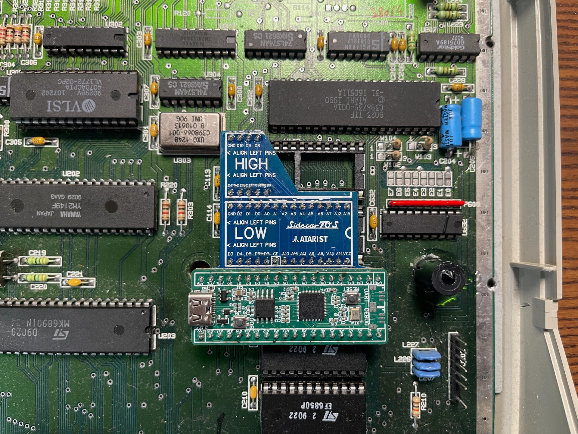
Atari STE
There are three jumpers that must be set to the correct position for the SidecarTridge TOS Emulator to work correctly. Since the SidecarTridge replaces the original 28-pin ROMs, the jumpers must be set to the same position as the original ROMs.
- W102 jumper: 2-3 position
- W103 jumper: 2-3 position
- W104 jumper: 2-3 position
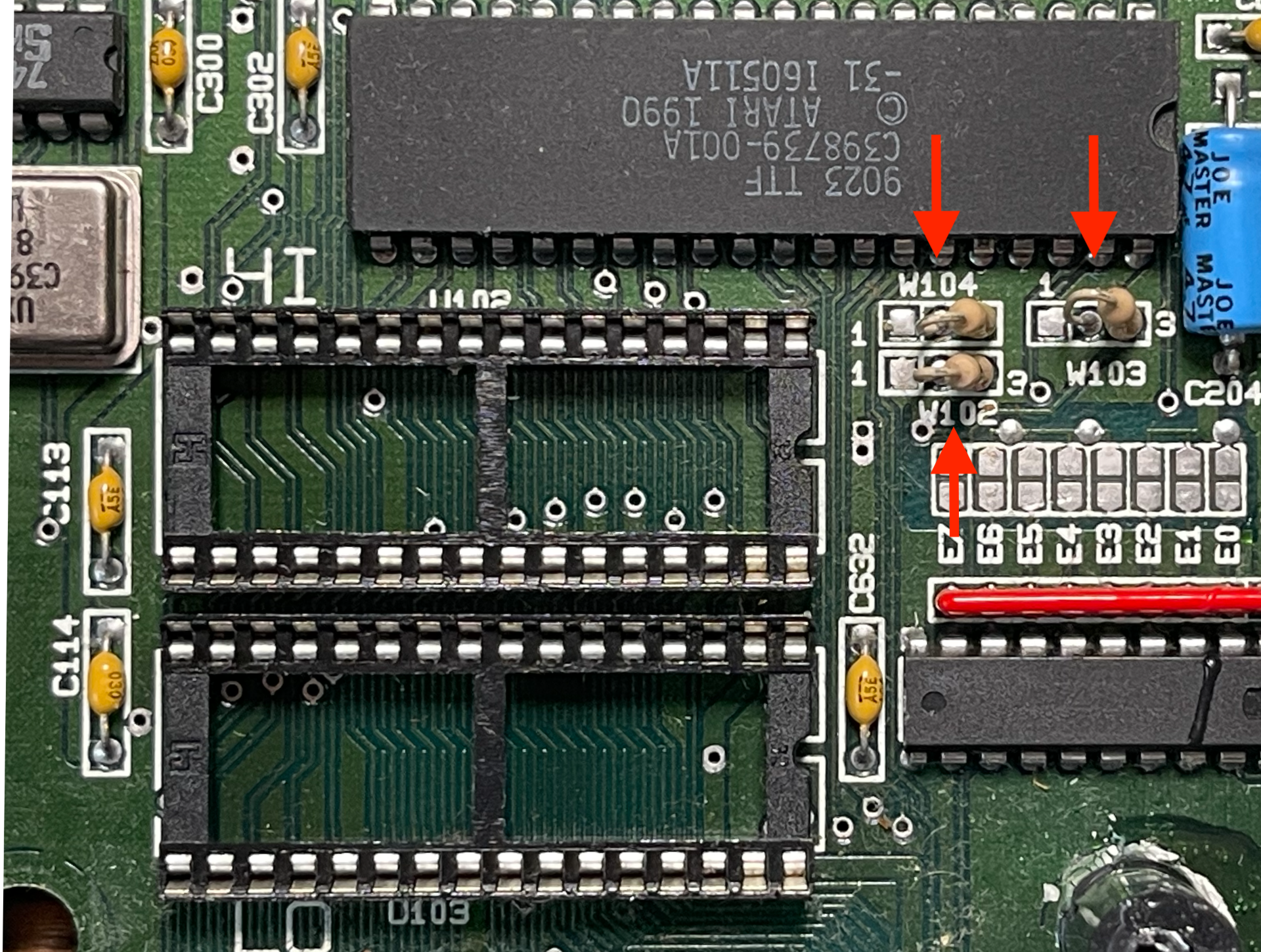
The Atari STE had a 0 Ohm resistor instead of a jumper bridge. It’s perfectly safe to replace it with a jumper bridge or a soldered wire.
The Atari STE has two 32-pin ROM sockets, but the SidecarTridge TOS Emulator only uses the first 28 pins. The last four pins are not connected, and it must be aligned to the left side of the socket.
Atari Mega STE
Following the same logic as the Atari STE, the jumpers must be set to the same position as the original ROMs.
- W201 jumper: 2-3 position
- W202 jumper: 2-3 position
- W203 jumper: NC (Not Connected)
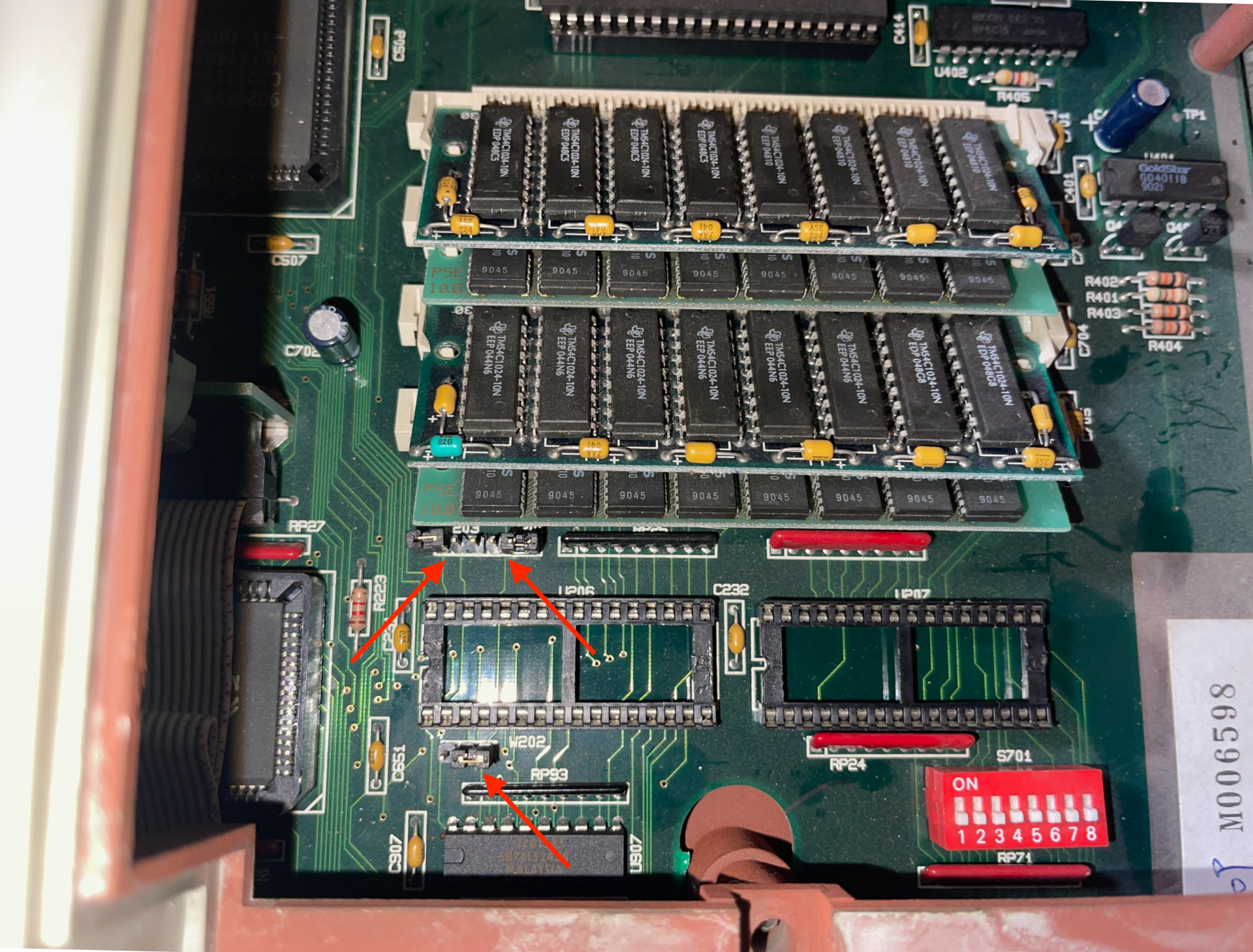
The Atari Mega STE also has two 32-pin ROM sockets, but the SidecarTridge TOS Emulator only uses the first 28 pins. The first four pins are not connected, and it must be aligned to the right side of the socket.
Plugging the SidecarTridge TOS Emulator
Depending on the Atari ST model, the SidecarTridge TOS Emulator carrier board must be connected to the motherboard in the correct orientation. The following steps provide guidance on connecting the emulator to the Atari ST motherboard securely.
Find the Correct Orientation
Atari C070789 Motherboards
The SidecarTridge carrier board has to be plugged into the ROM sockets marked as HI-0 and LO-0 on the Atari ST motherboard. The HI-0 socket is the one closest to the bottom edge of the motherboard.
The sockets are 28 pins wide like the SidecarTridge TOS Emulator, so it should be easy to align the emulator with the sockets.
Atari C070243 Motherboards
The SidecarTridge carrier board has to be plugged into the ROM sockets marked as HI-0 and LO-0 on the Atari ST motherboard. The LO-0 socket is the one closest to the bottom edge of the motherboard.
The sockets are 28 pins wide like the SidecarTridge TOS Emulator, so it should be easy to align the emulator with the sockets.
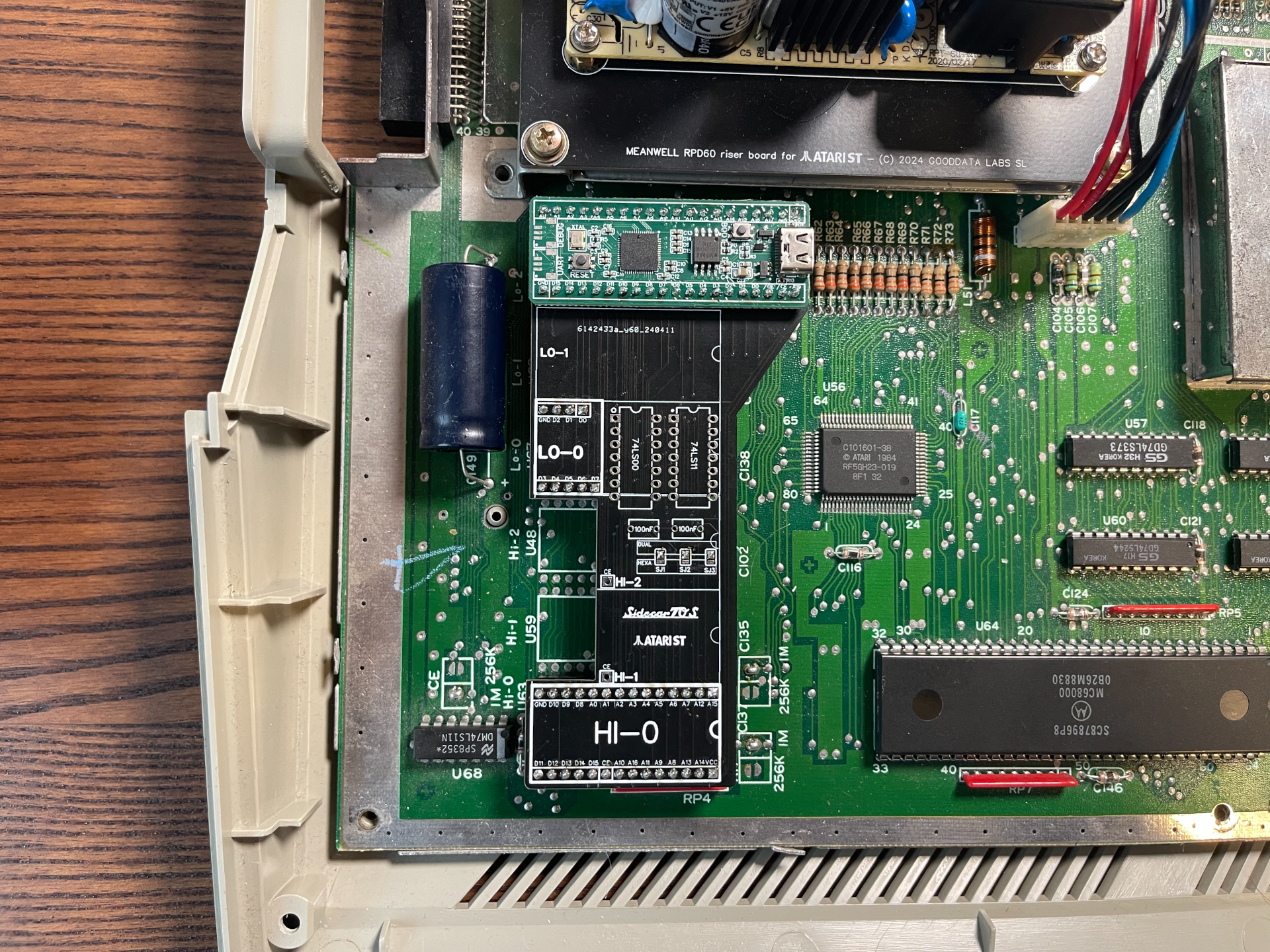
Atari C070523 Motherboards
The SidecarTridge carrier board has to be plugged into the ROM sockets marked as HI-2 and LO-2 on the Atari ST motherboard. That means the LOW part of the SidecarTridge TOS Emulator must be plugged into the socket closest to the bottom edge of the motherboard, and the HIGH part into the other socket.
The carrier board is placed below the Power Supply Unit, so it must be removed first to access the ROM sockets. The board is a low profile design to fit in the tight space below the PSU, but it is always a good idea to check for clearance before reassembling the Atari ST case.
Atari Mega ST
The SidecarTridge carrier board has to be plugged into the ROM sockets marked as FC-L and FC-H on the Atari Mega ST motherboard. The sockets are the two closest to the bottom edge of the motherboard.
Atari STE
The SidecarTridge carrier board has to be plugged into the ROM sockets marked as LO and HI. Insert the HIGH part of the SidecarTridge TOS Emulator into the HI socket and the LOW part into the LO socket. Don’t forget to align the SidecarTridge TOS Emulator to the left side of the socket!
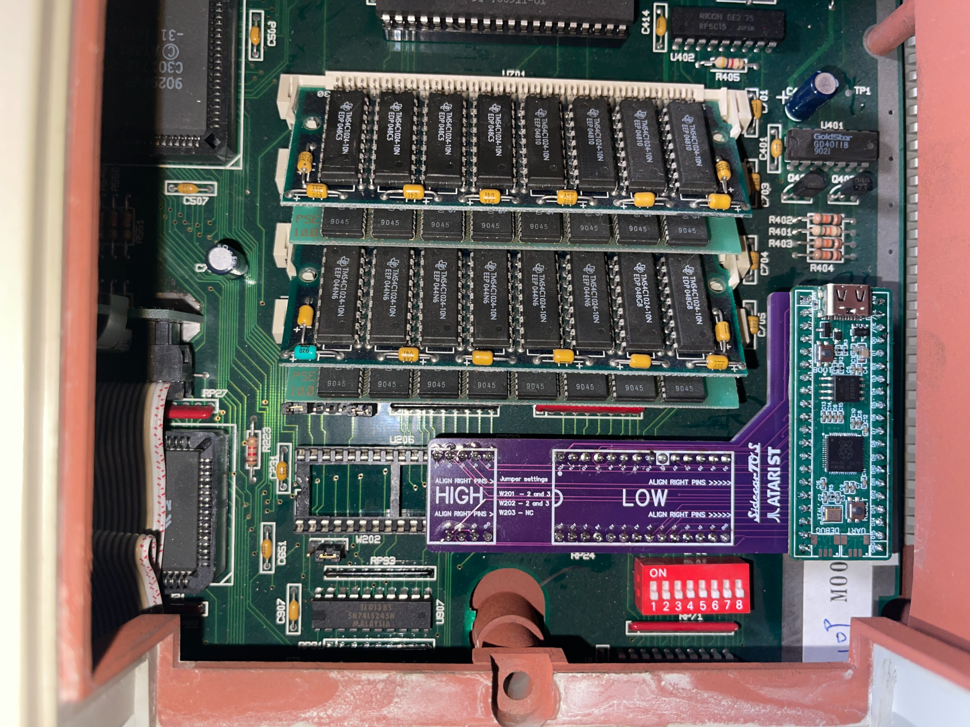
Atari Mega STE
The SidecarTridge carrier board has to be plugged into the ROM sockets marked as LO and HI. Insert the LOW part of the SidecarTridge TOS Emulator into the LO socket and the HIGH part into the HI socket. Don’t forget to align the SidecarTridge TOS Emulator to the right side of the socket!
Insert the Emulator
Gently press the SidecarTridge TOS Emulator into the ROM sockets. Apply even pressure on both sides to avoid bending any pins. Make sure it is fully seated and secure in the sockets. Try to insert all the pins at once, and don’t force it if it doesn’t fit.
Check Alignment
The Atari STE and MegaSTE have two 32-pin ROM sockets, but the SidecarTridge TOS Emulator only uses the first 28 pins. Make sure the SidecarTridge TOS Emulator is aligned correctly in the socket.
By following these steps, you will have successfully connected and secured the SidecarTridge TOS Emulator to your Atari ST, ensuring a stable and functional installation.
Closing the Atari ST Case
Test the unit before closing the case
Before reassembling the Atari ST, it is recommended to test the unit to ensure the SidecarTridge TOS Emulator is functioning correctly. Power on the Atari ST and verify that the SidecarTridge TOS Emulator is recognized and operational.
If the SidecarTridge TOS Emulator is not recognized or functioning correctly, power off the Atari ST and recheck the installation steps to identify and resolve any issues. If the problem persists, refer to the Troubleshooting section for further assistance.
Reassemble the Atari ST
Once the SidecarTridge TOS Emulator is confirmed to be working correctly, reassemble the Atari ST by reversing the steps taken to open the case.
Before closing the case, ensure there is no contacts of any of the elements of the SidecarTridge TOS Emulator with the metal shielding or any other component that could cause a short circuit.
Atari STE owners: Be careful when reassembling the Atari STE case and put a strip of insulating tape between the SidecarTridge TOS Emulator and the floppy drive to avoid any short circuit.