Board revisions
Table of contents
This page documents every hardware revision of the SidecarTridge Multi-device board. The revision number for your unit is printed on the silkscreen on the underside of the PCB.
Prefer video? Start here:
Revision 0: The original
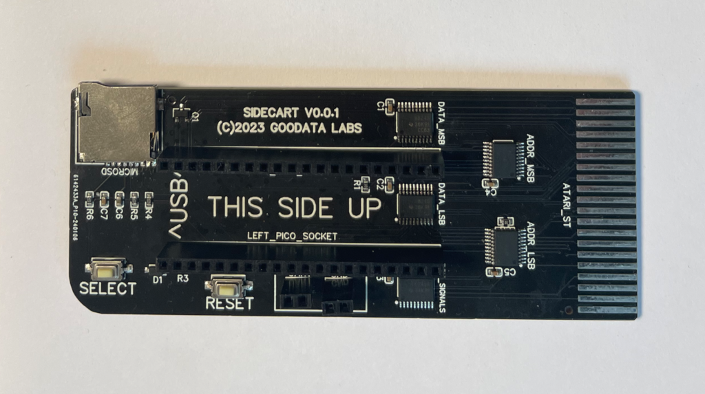
Owners of Multi-device boards purchased before February 2024 have Revision 0, the original model. It evolved from the launch prototype with only minor tweaks in order to manufacture a first batch of 25–30 boards. Demand quickly outpaced that plan. To keep the product affordable we stayed with a two-layer PCB, optimized trace widths for reliability, and stuck to a footprint defined by the cartridge connector, the Pico W dimensions, and straightforward panelization so shipping and production stayed economical.
Revision 1: The Hidden Failure
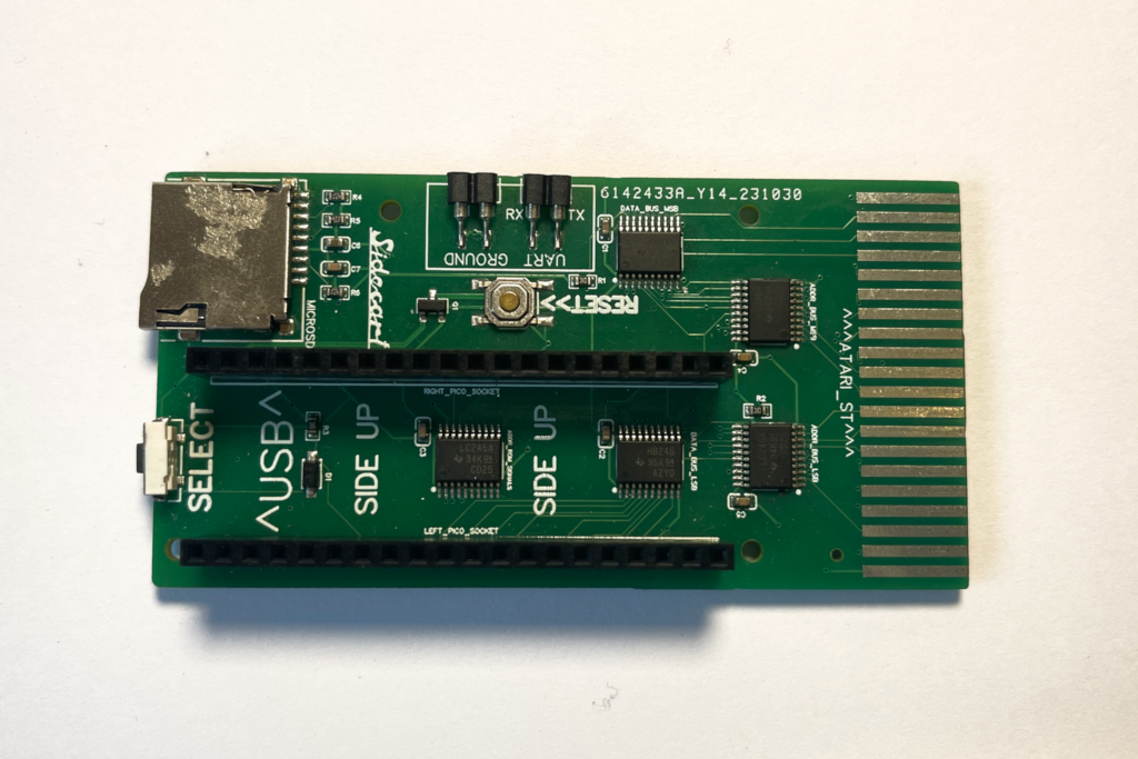
Revision 1 shrank the board to roughly 70 % of the original and moved to a four-layer PCB, repositioning the Pico W headers, SELECT button, and several passives to improve signal stability and mechanical rigidity. Those changes exposed new issues: some Atari ST models became finicky, the slimmer mounting holes were easier to crack, and existing Revision 0 cases no longer fit. The takeaway was clear—preserve backward compatibility whenever possible. Revision 1 never shipped commercially; only a few prototypes exist.
Revision 2: The Hybrid
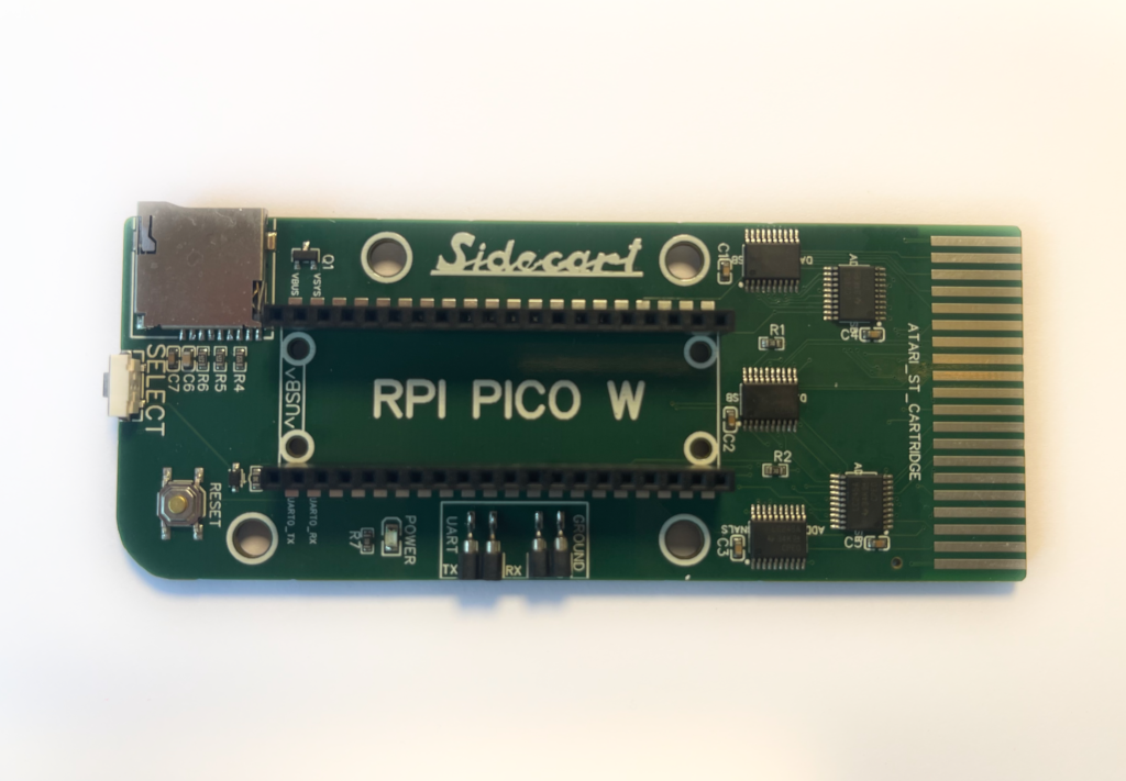
Revision 2.0
Shipping since February 2024, Revision 2.0 keeps the four-layer stack-up while returning to the original footprint so existing cases still fit. It adds larger case mounting holes, refines button placement, introduces a power LED, and supports a castellated Pico W option for lower-profile installs. The goal: blend the best of Revisions 0 and 1 without breaking anything owners already built.
Revision 2.1
Revision 2.1 makes two small tweaks to 2.0:
- The power LED resistor moves to 6.8 kΩ to reduce brightness.
- The Ground and UART headers return to their original configuration so JLPCB no longer charges the SMT pins as though they were through-hole components.
Revision 2.2.0
Revision 2.2.0 brings two notable upgrades:
- Dual USB-A power-only ports. Their rails are fused and protected with Schottky diodes to keep your Atari ST, the SidecarTridge, and connected USB devices safe.
- Dual JST-SH 2× male, 1.0 mm pitch connectors for the RESET and SELECT buttons, making it easier to add or remove front-panel controls inside enclosures.
Revision 2.2.1
Revision 2.2.1 adds a single JST-SH 3× male, 1.0 mm pitch connector for UART and GND, simplifying hookups to the Raspberry Pi Debug Probe.
Revision 2.3.0
Revision 2.3.0 refines the 2.2.x family to improve Pico W RF performance:
- Rerouted traces beneath the Pico W module.
- A larger keep-out (no-copper) area under the antenna window.
Revision 3.1
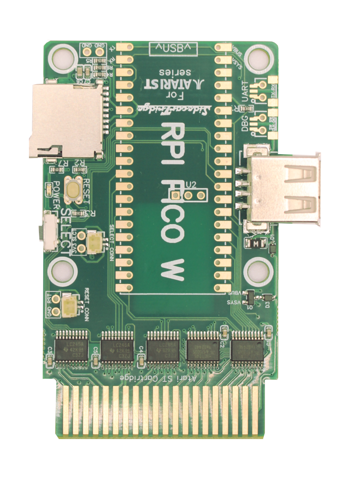
Revision 3.1 is a broad quality-of-life refresh:
- Smaller & more compact – Slimmer geometry makes installation easier without dropping features.
- Enhanced performance & stability – ENIG PCBs plus an optimized track layout improve signal integrity and reduce noise, especially in aging systems.
- Better power efficiency – Updated power distribution lowers consumption without compromising performance.
- Stronger Wi‑Fi – A larger copper window for the Pico W antenna delivers more reliable wireless links.
- Flexible Pico W integration – Supports both direct soldering and reflow assembly for the Pico W.
- Expanded maker connectivity – Offers JST and classic two-pin headers for RESET/SELECT, UART access, and full DEBUG connectivity.
Revision 3.2
Revision 3.2 focuses on power resilience for tired or marginal power supplies. It replaces the previous input protection circuit with a dual-voltage input switcher paired with an LM66200 ideal-diode controller. The new design automatically balances both power inputs, minimizes voltage drop, and shields the Multi-device from brown-outs when a computer’s PSU can no longer deliver a healthy 5 V rail.
Want to contribute?
You can contribute to this page. Please scroll to the bottom of the page and click on the “Edit this page on GitHub” link. You can then submit a pull request with your changes.