Programming SidecarTridge Multi-device
This section provides developers with in-depth guidance on programming the Multi-device board. It mainly covers the development of new applications or “microfirmware apps” for the RP2040 microcontroller. The guide is structured to help you understand the architecture of the Multi-device board, the microfirmware apps, and how to set up your development environment.
This guide applies to the new version 2.0 of the firmware in beta stage.
Table of contents
- Setting up the development environment
- Architecture review
- The Microfirmware apps
- How to Create a New Firmware Project Using
md-microfirmware-template - Microfirmware design
Setting up the development environment
Requirements
If you want to contribute to the projects as a developer, you’ll need a Raspberry Pi Pico Debug Probe.
The atarist-toolkit-docker is pivotal. Familiarize yourself with its installation and usage.
A
gitclient, command line or GUI, your pick.A Makefile attuned with GNU Make.
Visual Studio Code is highly recommended if you want to debug the code. You can find the configuration files in the
.vscodefolder.An Atari ST/STE/MegaST/MegaSTE computer. You can also use an emulator such as Hatari or STEEM for testing purposes, but you cannot really test any real functionality of the app without a real computer.
Setup a Raspberry Pi Pico development environment from scratch
If you are not familiar with the development on the Raspberry Pi Pico or RP2040, we recommend you to follow the Getting Started with Raspberry Pi Pico guide. This guide will help you to setup the Raspberry Pi Pico development environment from scratch.
We also think it’s very important to setup the picoprobe debugging hardware. The picoprobe is a hardware debugger that will allow you to debug the code running on the Raspberry Pi Pico. You can find more information in this two excellent tutorials from Shawn Hymel:
- Raspberry Pi Pico and RP2040 - C/C++ Part 1: Blink and VS Code
- Raspberry Pi Pico and RP2040 - C/C++ Part 2 Debugging with VS Code
To support the debugging the SidecarTridge has four pins that are connected to the picoprobe hardware debugger. These pins are:
- UART TX: This pin is used to send the debug information from the RP2040 to the picoprobe hardware debugger.
- UART RX: This pin is used to send the debug information from the picoprobe hardware debugger to the RP2040.
- GND: Two ground pins. One MUST connect to the GND of the Raspberry Pi Pico W (the middle connector between DEBUG and SWCLK and SWDIO) and the other MUST connect to the GND of the picoprobe hardware debugger. Don’t let this pins floating, otherwise the debugging will not work.
Also a good tutorial about setting up a debugging environment with the picoprobe can be found in the Raspberry Pi Debug Probe tutorial.
Trying to develop software for this microcontroller without the right environment is frustrating and a waste of time. So please, take your time to setup the development environment properly. It will save you a lot of time in the future.
Configure environment variables
The following environment variables are required to be set:
PICO_SDK_PATH: The path to the Raspberry Pi Pico SDK.PICO_EXTRAS_PATH: The path to the Raspberry Pi Pico Extras SDK.FATFS_SDK_PATH: The path to the FatFS SDK.
This repository contains subrepos pointing to these SDKs in root folder.
All the compile, debug and build scripts use these environment variables to locate the SDKs. So it’s very important to set them properly. An option would be to set them in your .bashrc file if you are using Bash, or in your .zshrc file if you are using ZSH.
Configure Visual Studio Code
To configure Visual Studio Code to work with the Raspberry Pi Pico, please follow the Raspberry Pi Pico and RP2040 - C/C++ Part 2 Debugging with VS Code tutorial.
Linux/macOS
export ARM_GDB_PATH=/path/to/your/arm-toolchain
export PICO_OPENOCD_PATH=/path/to/openocd/tcl
Windows (PowerShell)
$env:ARM_GDB_PATH="C:\Path\to\your\arm-toolchain"
$env:PICO_OPENOCD_PATH="C:\Path\to\openocd\tcl"
Windows (CMD)
set ARM_GDB_PATH=C:\Path\to\your\arm-toolchain
set PICO_OPENOCD_PATH=C:\Path\to\openocd\tcl
Install Visual Studio Code extensions
Architecture review
Before starting with the programming of the Multi-device board, it is important to understand the two basic ROM emulation modes available and describe in detail in the section Architecture and Design. To summarize the two modes:
- Full ROM emulation mode: the Atari ST effortlessly reads the shared RAM memory as if perusing through a full address range of the ROM memory expansion, void of any perceptible differences. The Atari ST is NOT aware of the existence of the Multi-device.
- Hybrid ROM emulation mode: the Atari ST accesses the shared RAM memory but only a specific subrange of addresses of the ROM memory expansion. The other subranges are allocated to implement a command protocol between the host and the microcontroller, fostering an interactive session with applications running on the RP2040. The Atari ST is aware of the existence of the Multi-device.
The Microfirmware apps
What is a Microfirmware app?
The Microfirmware app is designed to run as a stand alone rp2040/rp235x plus the computer side firmware that communicates with it. The key components include:
Microfirmware app Core
The heart of the system, responsible for handling the micro SD card, communicating with the remote computer and providing the web interface if needed.Global Settings
Stored in flash memory, these settings apply to the entire device and its apps. The microfirmware app does only read the settings, it does not modify them.Local Settings
Each app has its own isolated configuration stored in flash memory, ensuring app-specific settings remain independent. This section is read and written by the app.Computer firmware
The Booster app uses the remote computer as the terminal and implements the logic to communicate with the microfirmware app. Since it runs in ROM, it can be challenging to debug and develop it. Try to put all the debugging code in the microfirmware app and use the computer as a terminal.
General Memory Map
The Pico W and Pico 2W feature a 2MB flash memory, structured as follows:
+-----------------------------------------------------+
|                                                     |
|              MICROFIRMWARE APP (1152K)              |  0x10000000
|          Active microfirmware flash space           |
|                                                     |
+-----------------------------------------------------+
...
+-----------------------------------------------------+
|                                                     |
|                  CONFIG FLASH (120K)                |  0x101E0000
|             Microfirmwares configurations           |
|                                                     |
+-----------------------------------------------------+
|                                                     |
|              GLOBAL LOOKUP TABLE (4K)               |  0x101FE000
|  Microfirmwares mapping to configuration sectors    |
|                                                     |
+-----------------------------------------------------+
|                                                     |
|              GLOBAL SETTINGS (4K)                   |  0x101FF000
|           Device-wide configurations                |
|                                                     |
+-----------------------------------------------------+
How to Create a New Firmware Project Using md-microfirmware-template
This guide walks you through the steps to clone and configure a new firmware project for the SidecarTridge Multi-device platform, using md-rtc-emulator as an example. You can find the template repository in https://github.com/sidecartridge/md-microfirmware-template
1. Create a GitHub Repository from the Template
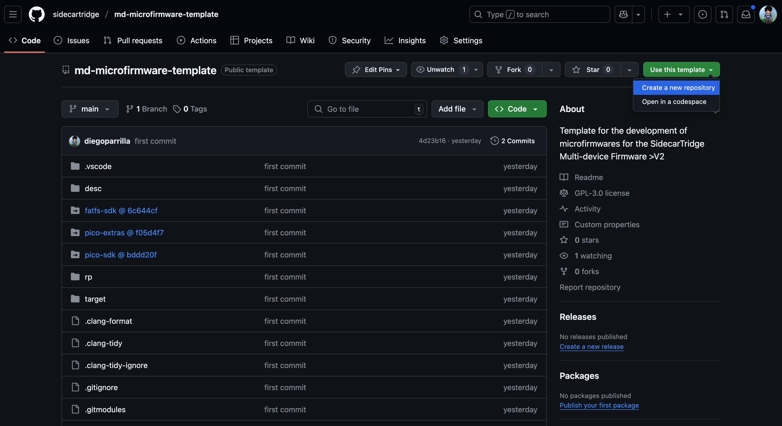
- Navigate to the
md-microfirmware-templaterepository. - Click the green “Use this template” button and select “Create a new repository”.
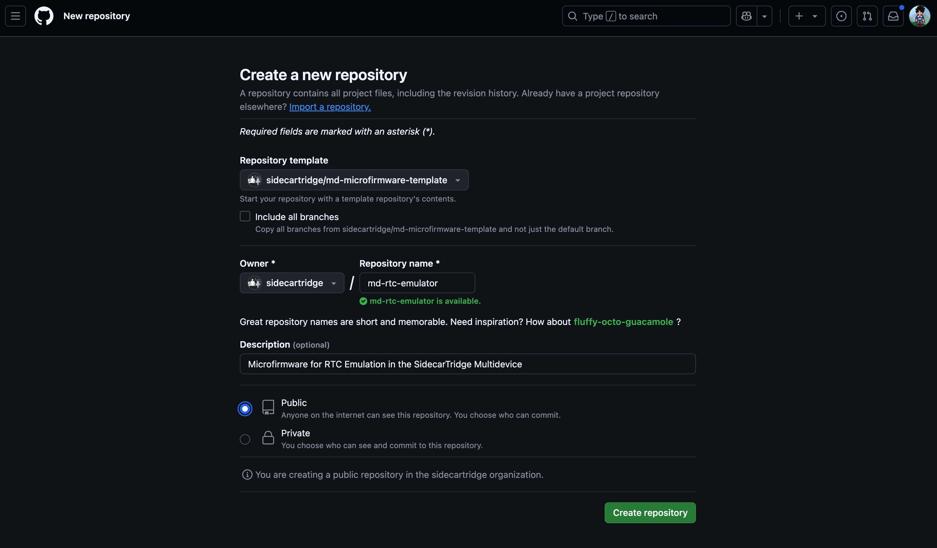
- Set the repository name to
md-rtc-emulator(or any other descriptive name). - Ensure visibility is set to Public or Private as needed.
- Click “Create repository”.
2. Clone Your New Repository Locally
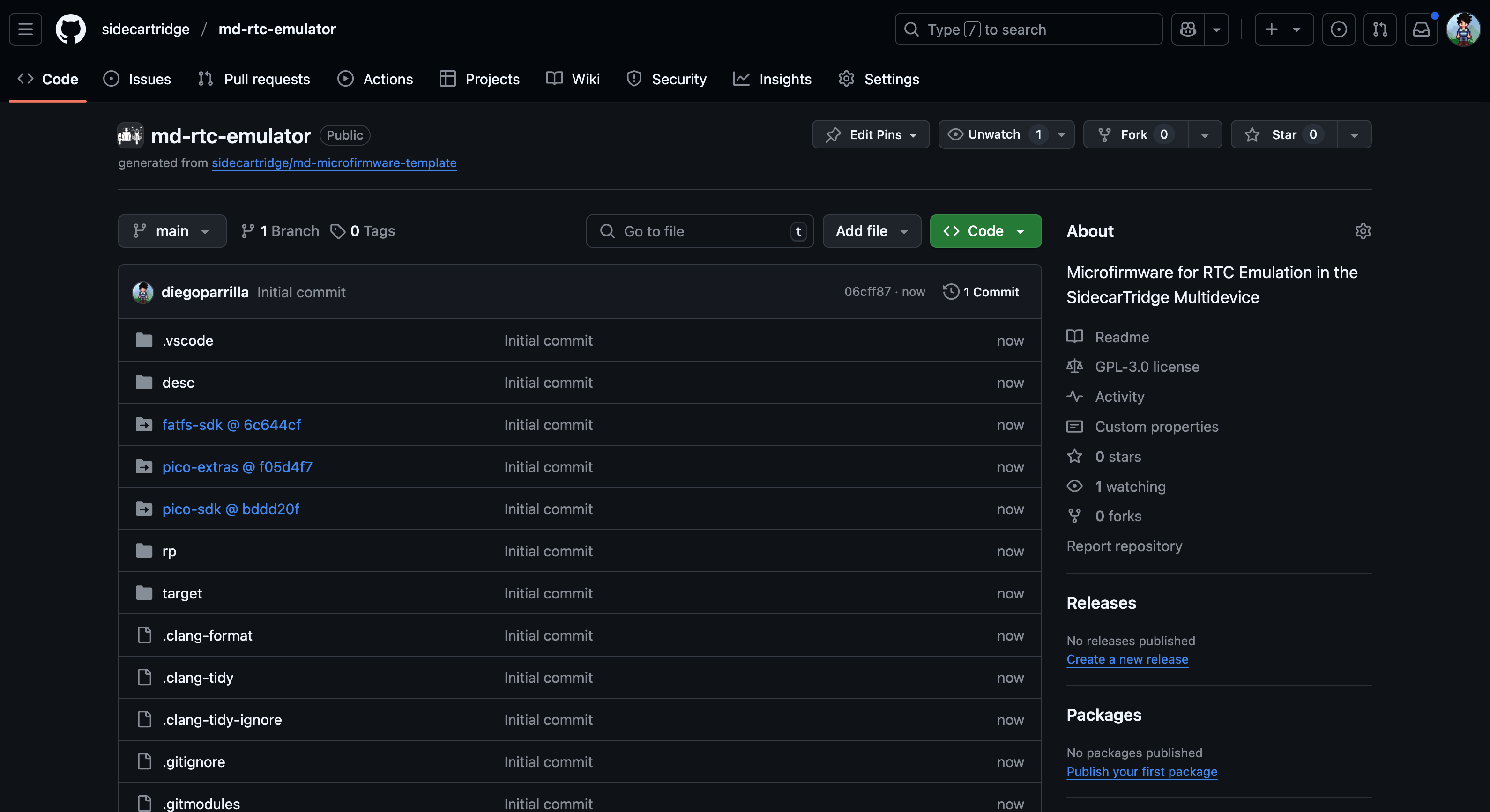
Pick the URL of the new repository you just created.
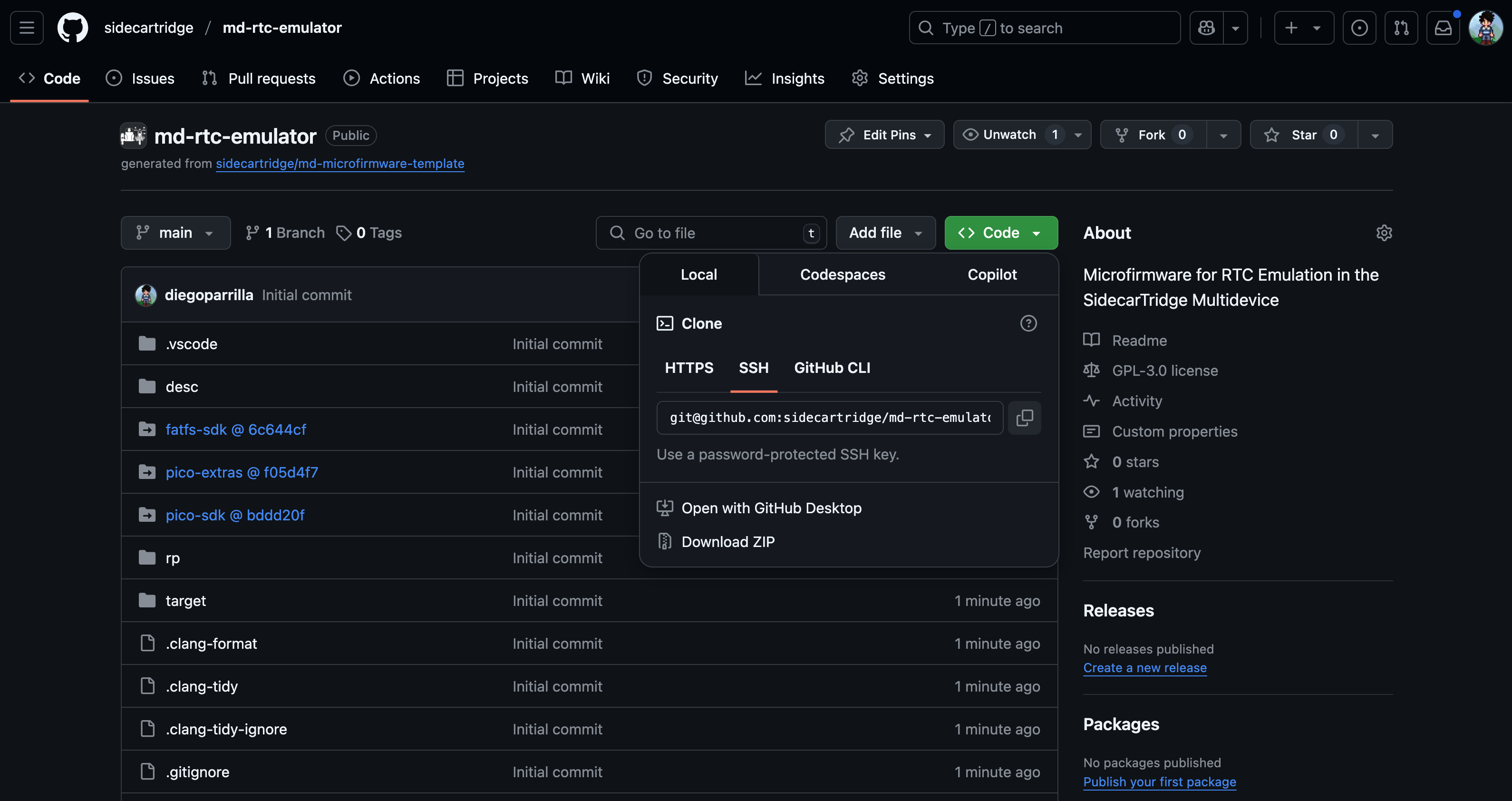
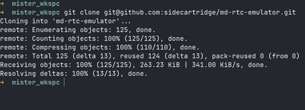
Clone your new repo using SSH or HTTPS:
git clone git@github.com:sidecartridge/md-rtc-emulator.git
cd md-rtc-emulator
3. Initialize Git Submodules
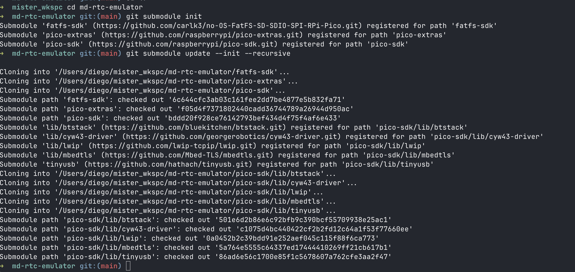
Run the following commands to initialize all required submodules:
git submodule init
git submodule update --init --recursive
This pulls in essential dependencies like:
pico-sdkpico-extrasfatfs-sdk
4. Build the Project
The main build script is build.sh, located in the root directory of the project executes both buid.sh scripts in the /rp and /target folders. The script in the /rp folder builds the microfirmware app for the RP2040, while the script in the /target folder builds the computer firmware for the target computer.
The parameters for the build script are:
- The target device. In this version it can be
pico_w. - The build type. It can be
debugorrelease.debugwill create a version with debug symbols and output traces through the UART.releasewill create a version without debug symbols and output traces. - The UUID of the app. This is a valid UUID v4 that will be used to identify the app. It must be unique for each app. The UUID is used to create the lookup table in the flash memory and to create the app info file. During development time, you can use the UUID
44444444-4444-4444-8444-444444444444to test the app.
./build.sh pico_w debug 44444444-4444-4444-8444-444444444444
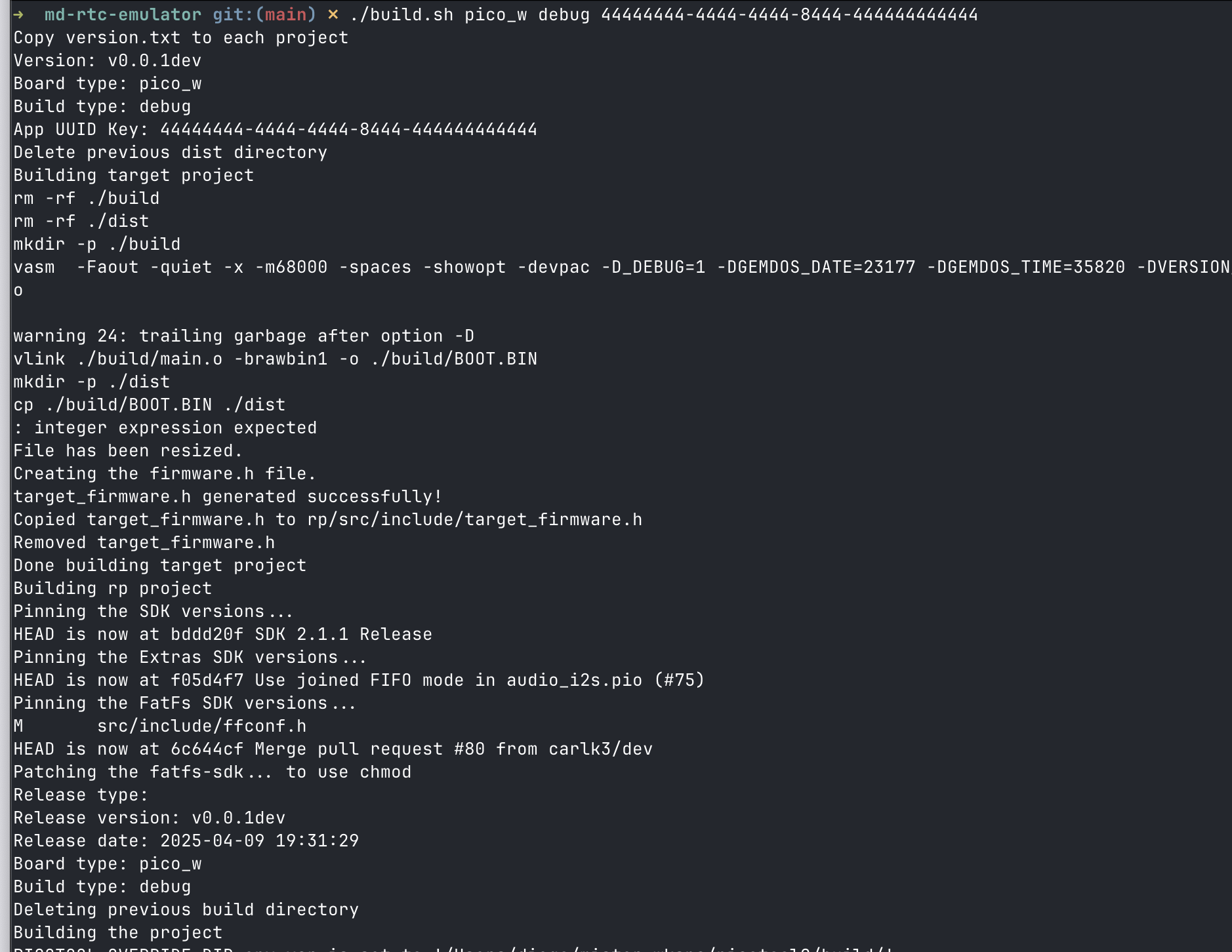
and after a few seconds, you will see the build process output in the terminal.
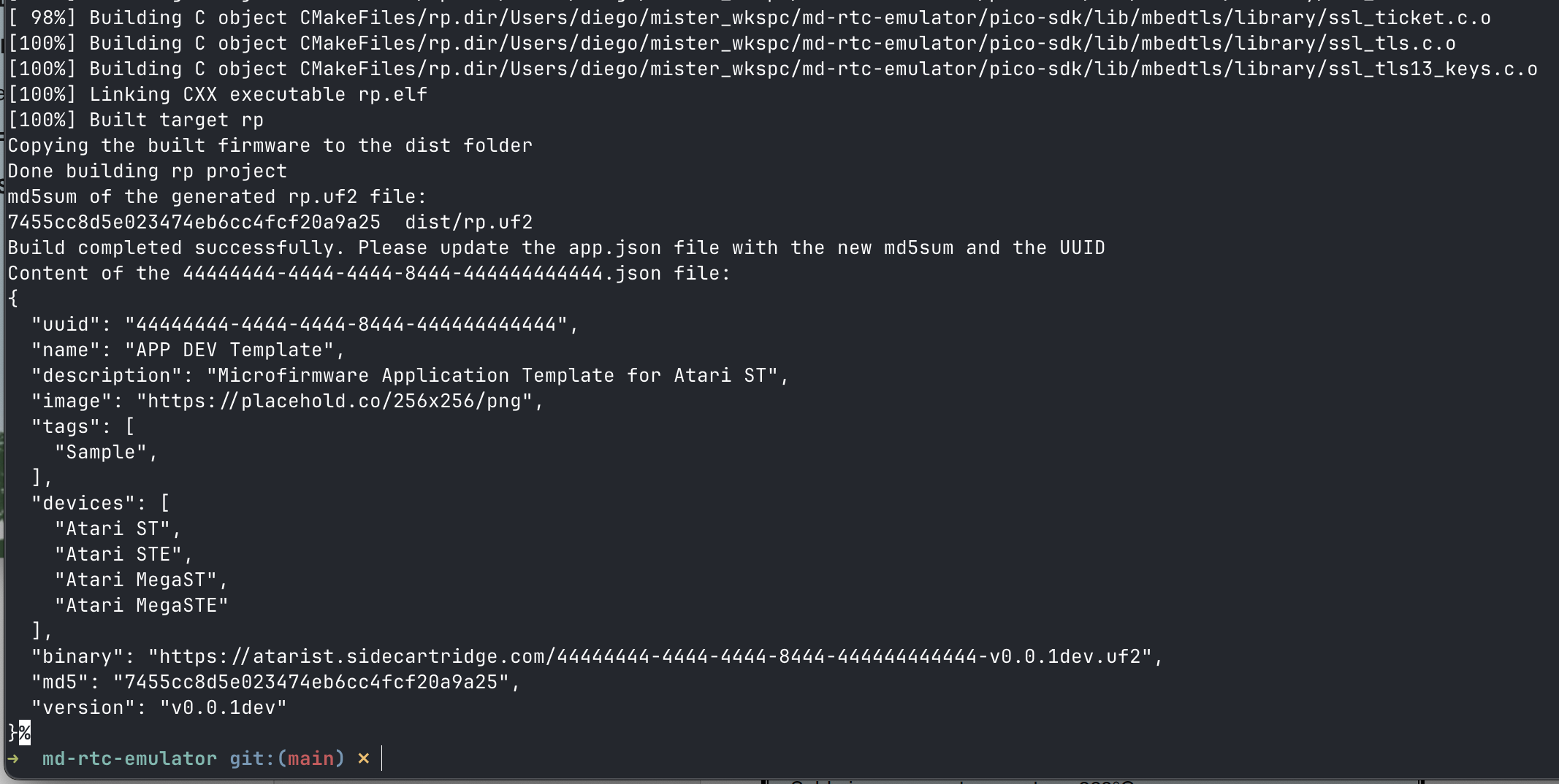
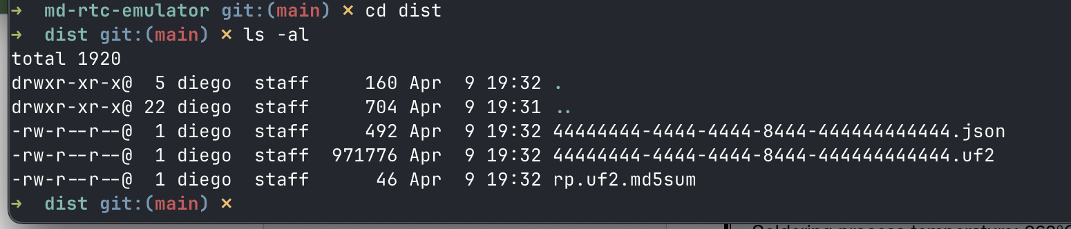
In the /dist folder, you will find:
- the
44444444-4444-4444-8444-444444444444.uf2binary file with the microfirmware app. - the
44444444-4444-4444-8444-444444444444.jsonfile with the app information. This file is used by the Booster app to identify the app and show it in the list of apps. - the
44444444-4444-4444-8444-444444444444.md5file with the md5 checksum of the binary file. This file is used by the Booster app to verify the integrity of the binary file.
The developer can now deploy the uf2 file to the Raspberry Pi Pico W using the picotool command line tool. For example:
picotool load dist/44444444-4444-4444-8444-444444444444.uf2
And rebooting the board connected to the computer will load the new firmware if the uf2 file is valid and in the Booster app the developer has selected the option to launch the DEV APP
But this is not a very quick way to develop a firmware. It’s much easier to use the picoprobe hardware debugger and Visual Studio code to debug the code.
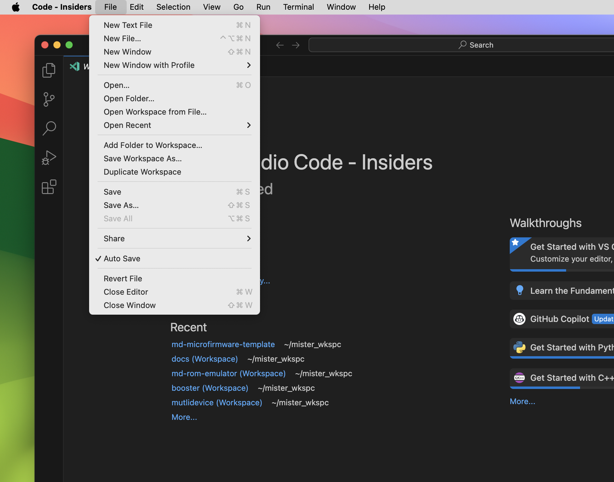
5. Open the Project in VS Code
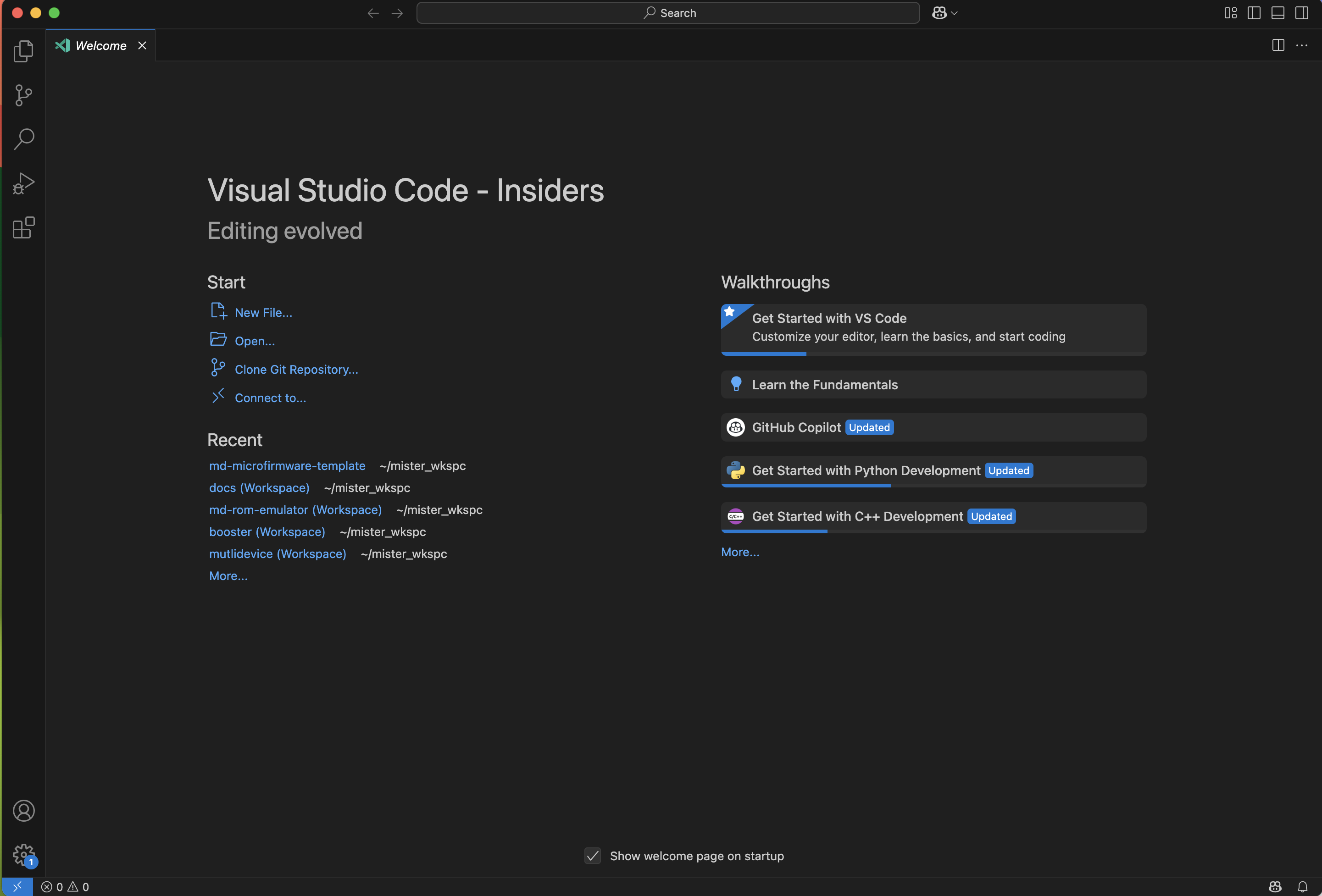
Open the project folder in Visual Studio Code or VS Code Insiders using the entry in the menu File → Add Folder to Workspace... and select the folder you just cloned.
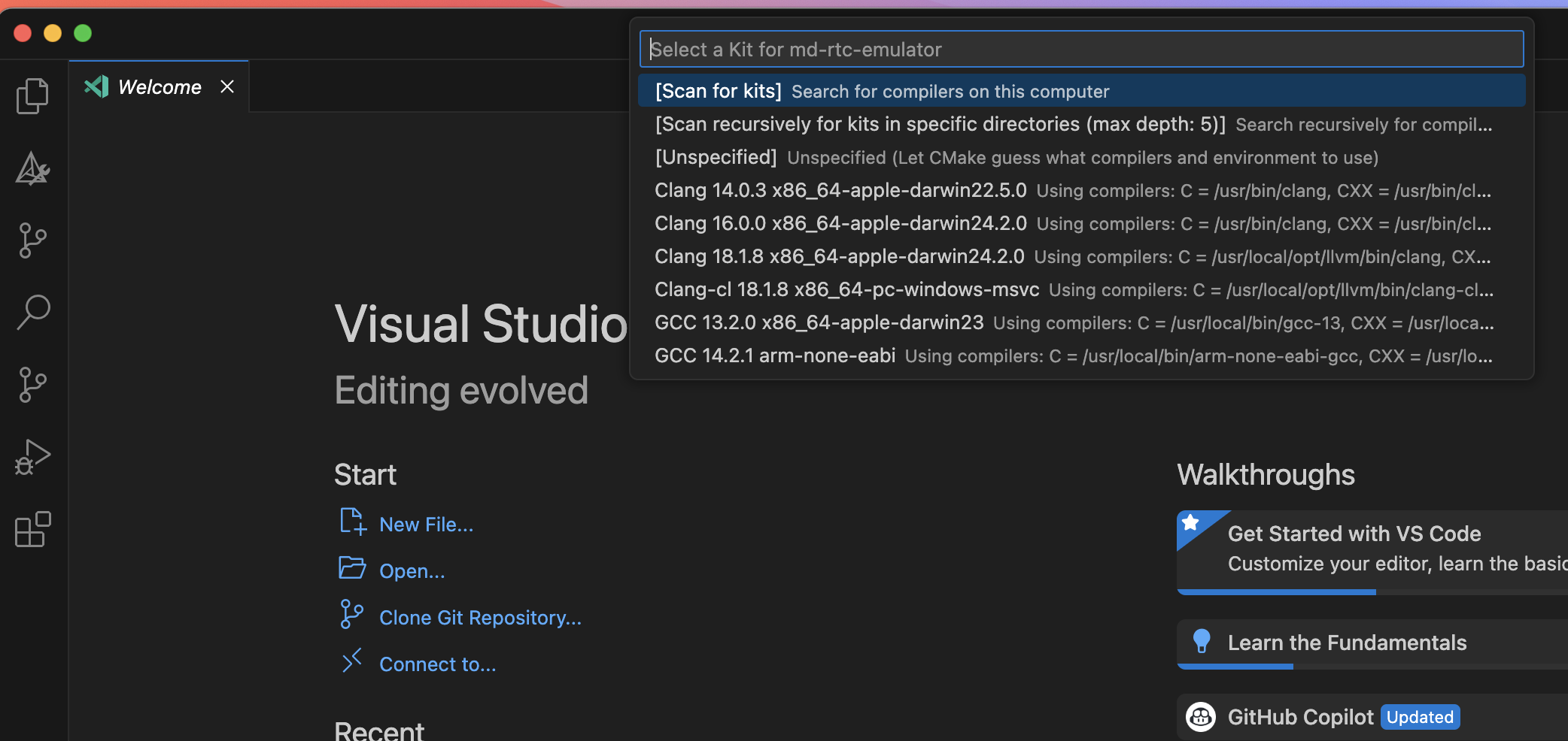
Use the CMake Tools extension to select a build environment:
- Open the command palette → “CMake: Select a Kit”
- Choose a compiler (e.g.,
GCC 14.2.1 arm-none-eabi)
Ensure that the Auto Save option is enabled for smooth development.
6. Adjust the debugging options in Visual Studio code
The .vscode folder contains the configuration files for Visual Studio Code. Please modify them as follows:
launch.json: Modify thegdbPathproperty to point to thearm-none-eabi-gdbfile in your computer.launch.json: Modify thesearchDirproperty to point to the/tclfolder inside theopenocdproject in your computer.settings.json: Modify thecortex-debug.gdbPathproperty to point to thearm-none-eabi-gdbfile in your computer.
These variables allow the debugger to automatically find GDB and OpenOCD without modifying the launch.json file every time you switch environments.
Microfirmware design
Libraries and components
External Libraries
These libraries are in different repositories and are included as submodules:
- Pico-SDK: The official Raspberry Pi Pico SDK, providing essential libraries and tools for development.
- Pico-Extras: A collection of additional libraries and utilities for the Pico platform, enhancing functionality and ease of use.
- no-OS-FatFS-SD-SDIO-SPI-RPi-Pico: A library for interfacing with micro SD cards using the SPI protocol, enabling file system access and management.
Internal Libraries
These libraries are part of the rp project and are included in the repository:
- httpc: A lightweight HTTP client library for making requests to web servers, used for fetching updates and resources.
- settings: The
rp-settingslibrary. - u8g2: A graphics library for rendering text and images on various display types, used for the external display support in the Booster Core.
Project structure
Two different architectures
The project is structure in two very different folders with code:
/rp: where the code deployed in the RP2040 is located. This code is compiled and linked with the RP2040 SDK./target: where the code for the target computer is located. The spirit of this folder is contain the code that will be compiled for the remote computer target. In this project the code is foratarist, so a folder/target/ataristis created. The code in this folder is compiled with theatarist-toolkit-dockerproject. This project is a docker image that contains all the tools needed to compile the code for the Atari ST/STE/MegaST/MegaSTE computers.
The binary file generated by the build.sh file in the /target/atarist folder must create a C array that should be included in the /rp/src/include folder with the filename target_firmware.h. The binary content of this array should be copied to the ROM_IN_RAM section of the RAM.
The goal of this architecture is to have a clean separation between the code that runs in the RP2040 and the code that runs in the remote computer. Starting in version 2 of the firmware we will try to put as much code as possible in the rp folder. In 2025 is much easier to develop code for the RP2040 than for the Atari ST/STE/MegaST/MegaSTE computers. Hence, the code for the remote computers (Atari ST or any other future computers that we want to support) should be as minimal as possible and strictly focused on implementing the emulation of the targe device (ROM, Floppy, HD, RTC, Network, etc) and the communication with the RP2040.
The RP2040 and RP235x codebase
The code in the /rp folder is the code that will be compiled and linked with the RP2040 SDK. This code is responsible for handling the micro SD card, communicating with the remote computer, networking and providing the web interface if needed.
Apart from the libraries described in the previous sections (Pico-SDK, Pico-Extras, no-OS-FatFS-SD-SDIO-SPI-RPi-Pico, httpc, settings and u8g2), the code in the /rp folder is composed os several boilerplate modules that are used to implement the basic features of the microfirmware app. These modules are:
aconfig.c
This module is responsible for handling the configuration of the microfirmware app. It uses the settings library to store and retrieve the configuration settings. The configuration settings are stored in flash memory and are used to configure the microfirmware app.
Each app has its own configuration settings. To avoid misconfigurations during upgrades or downgrades, the list of default settings is stored in the defaultEntries array in this file. It is mandatory to define here the default settings for the app.
In the template app there is only an example of the settings:
static SettingsConfigEntry defaultEntries[] = {
    {ACONFIG_PARAM_FOLDER, SETTINGS_TYPE_STRING, "/test"},
    {ACONFIG_PARAM_MODE, SETTINGS_TYPE_INT, "255"},  // 255: Menu mode
};
The local settings has to be initialized in the main.c file of the app once we have already verified that the app uuid key of the app exists and it is correct. The CURRENT_APP_UUID_KEY is the uuid of the app that is being executed.
The aconfig_init function will check if the app uuid key exists in the lookup table. If it does not exist, it will return an error and the app will be redirected to the booster. If it exists, it will check if the settings are already initialized. If they are not initialized, it will initialize them with the default values defined in the defaultEntries array.
// If we are here, it means the app uuid key is correct. So we can read or
// initialize the app settings
err = aconfig_init(CURRENT_APP_UUID_KEY);
switch (err) {
  case ACONFIG_SUCCESS:
    DPRINTF("App settings found and already initialized\n");
    break;
  case ACONFIG_APPKEYLOOKUP_ERROR:
    // The app key is not found in the lookup table. Go to booster.
    DPRINTF("App key not found in the lookup table. Go to BOOSTER.\n");
    reset_jump_to_booster();
    // We should never reach this point
    break;
  case ACONFIG_INIT_ERROR:
    // No settings found. First time the app is executed? Then initialize the
    // settings
    DPRINTF("App settings not initialized. Initialize them first\n");
    err = settings_save(aconfig_getContext(), true);
    if (err < 0) {
      // Something went wrong saving the settings. Go to booster.
      DPRINTF("Error saving settings. Go to BOOSTER.\n");
      reset_jump_to_booster();
      // We should never reach this point
    }
    // Show the settings
    settings_print(aconfig_getContext(), NULL);
    break;
}
After the succesful initialization of the settings, the app can use the aconfig_getContext() function to get the context of the settings and use it to read and write the settings, as usual.
  SettingsConfigEntry *appMode =
      settings_find_entry(aconfig_getContext(), ACONFIG_PARAM_MODE);
  if (appMode == NULL) {
    DPRINTF(
        "ACONFIG_PARAM_MODE not found in the configuration.\n");
  }
blink.c
This module is responsible for handling the blinking of the LED on the Raspberry Pi Pico W. It uses the pico-sdk library to control the GPIO pins and implement the blinking functionality. The LED is used to indicate the status of the microfirmware app.
display.c
This module is responsible for handling the external display. It uses the u8g2 library to control the display and implement the functionality.
In this version it wraps the u8g2 library to provide a simple interface to draw text, scroll up texts and draw images on the display. Since it is focused in the first version for Atari ST computers, it creates a 320x200 monochrome display with a 8x8 font, indpendently of the real display used: Low res or High res. We can think this as a frame buffer that will be used to draw the text and images. The code in the /target folder will be responsible for reading this frame buffer and sending the data to the Atari ST computer memory screen.
The display.c should be wrapped by a more high level display manager that will be responsible for handling no only the text but also the keyboard input and the mouse input, if necessary. In the template app this is in the display_term.c file.
display_term.c
This module is responsible for implementing a simple terminal interface to display text on the external display. It uses the display.c module to draw the text and implement the functionality, and also the tprotocol.h header file to implement the communication protocol with the remote computer; the core of the microfirmware app.
This modelo implements the commands that listen for remote keystrokes and convert them into ASCII characters that combined form the terminal commands. In this version the terminal commands are very simple and only implement the basic functionality to manage the local settings, exit the app or launch the Booster app.
download.c
As the name suggests, this module is responsible for downloading any kind of file from a remote HTTP/S server and saving it to the micro SD card. It uses the httpc library to implement the functionality.
The file download is implemented aysnchronously, so the app can continue running while the file is being downloaded. To download a file, it must be polled in a loop. This is an example from the md-rom-emulator microfirmware app:
  DPRINTF("Start the app loop here\n");
  absolute_time_t startDownloadTime =
      make_timeout_time_ms(DOWNLOAD_DAY_MS);  // Future time
  while (getKeepActive()) {
#if PICO_CYW43_ARCH_POLL
    network_safe_poll();
    cyw43_arch_wait_for_work_until(wifi_scan_time);
#else
    sleep_ms(SLEEP_LOOP_MS);
#endif
    // Check remote commands
    term_loop();

    // Check the download status
    switch (download_getStatus()) {
      case DOWNLOAD_STATUS_REQUESTED: {
        startDownloadTime = make_timeout_time_ms(
            DOWNLOAD_START_MS);  // 3 seconds to start the download
        download_setStatus(DOWNLOAD_STATUS_NOT_STARTED);
        break;
      }
      case DOWNLOAD_STATUS_NOT_STARTED: {
        if ((absolute_time_diff_us(get_absolute_time(), startDownloadTime) <
             0)) {
          download_err_t err = download_start();
          if (err != DOWNLOAD_OK) {
            DPRINTF("Error downloading app. Drive to error page.\n");
          }
        }
        break;
      }
      case DOWNLOAD_STATUS_IN_PROGRESS: {
        download_poll();
        break;
      }
      case DOWNLOAD_STATUS_COMPLETED: {
        // Save the app info to the SD card
        download_finish();
        download_confirm();
        download_setStatus(DOWNLOAD_STATUS_IDLE);
        break;
      }
    }
  }
emul.c
The critical path of the emulation is implemented in this module. After the initial checks in the main.c file, we implement in this module the initialization of the different services that are needed to run the microfirmware app, and then we enter in the main loop of the app.
The critical path is in the emul_start function called from the main.c file. This functions performs the following actions in this order:
- Check if the host device must be initialized to perform the emulation of the device, or start in setup/configuration mode.
- Initialiaze the normal operation of the app (go to step 4), unless the configuration option says to start the config app or a SELECT button is (or was) pressed to start the configuration section of the app.
- If we are here, it means the app is not in emulation mode, but in setup/configuration mode.
- During the setup/configuration mode, the driver code must interact with the user to configure the device. To simplify the process, the terminal emulator is used to interact with the user.
- Init the sd card
- Init the network, if needed
- Now complete the terminal emulator initialization
- Main loop
- If exited main loop, send START computer command
- Not only exit the main loop, but send RESET computer command
The step 3 can need multiple services, so it could steps 5 to 8 too.
To emulate a service or device of the remote computer in this module we will have to orchestrate the difference services to accomplish the task. As a rule of thumb, reuse as much boiler plate code as possible.
gconfig.c
This module is responsible for handling the global settings of the microfirmware app. It uses the settings library to store and retrieve the global settings. The global settings are stored in flash memory and are used to configure the microfirmware app.
In the global settings we have the parameters that are used for all the apps installed. To avoid misconfigurations during upgrades or downgrades, the list of global default settings is stored in the defaultEntries array and is a copy of the values found in the booster project.
static SettingsConfigEntry defaultEntries[] = {
    {PARAM_APPS_FOLDER, SETTINGS_TYPE_STRING, "/apps"},
    {PARAM_APPS_CATALOG_URL, SETTINGS_TYPE_STRING,
     "http://atarist.sidecartridge.com/apps.json"},
    {PARAM_BOOT_FEATURE, SETTINGS_TYPE_STRING, "CONFIGURATOR"},
    {PARAM_HOSTNAME, SETTINGS_TYPE_STRING, "sidecart"},
    {PARAM_SAFE_CONFIG_REBOOT, SETTINGS_TYPE_BOOL, "true"},
    {PARAM_SD_BAUD_RATE_KB, SETTINGS_TYPE_INT, "12500"},
    {PARAM_WIFI_AUTH, SETTINGS_TYPE_INT, "0"},
    {PARAM_WIFI_CONNECT_TIMEOUT, SETTINGS_TYPE_INT, "30"},
    {PARAM_WIFI_COUNTRY, SETTINGS_TYPE_STRING, "XX"},
    {PARAM_WIFI_DHCP, SETTINGS_TYPE_BOOL, "true"},
    {PARAM_WIFI_DNS, SETTINGS_TYPE_STRING, "8.8.8.8"},
    {PARAM_WIFI_GATEWAY, SETTINGS_TYPE_STRING, ""},
    {PARAM_WIFI_IP, SETTINGS_TYPE_STRING, ""},
    {PARAM_WIFI_MODE, SETTINGS_TYPE_INT, "0"},
    {PARAM_WIFI_NETMASK, SETTINGS_TYPE_STRING, ""},
    {PARAM_WIFI_PASSWORD, SETTINGS_TYPE_STRING, ""},
    {PARAM_WIFI_POWER, SETTINGS_TYPE_INT, "0"},
    {PARAM_WIFI_RSSI, SETTINGS_TYPE_BOOL, "true"},
    {PARAM_WIFI_SCAN_SECONDS, SETTINGS_TYPE_INT, "10"},
    {PARAM_WIFI_SSID, SETTINGS_TYPE_STRING, ""}};
The global settings has to be initialized in the main.c file right after changing the clock speed and voltage. It checks if the current app uuid key is the same as the one in the global settings. If it is not, it will be redirected to the booster. If it is, it will check if the settings are already initialized. If they are not initialized, it will initialize them with the default values defined in the defaultEntries array.
  // Load the global configuration parameters
  int err = gconfig_init(CURRENT_APP_UUID_KEY);
  // If the global settings are not intialized, jump to the booster app to
  // initialize them
  if (err < 0) {
    DPRINTF("Settings not initialized. Jump to Booster application\n");
    reset_jump_to_booster();
  }
Then, access the global settings using the gconfig_getContext() function to get the context of the settings and use it to read and write the settings, as usual.
  SettingsConfigEntry *appsFolder =
      settings_find_entry(gconfig_getContext(), PARAM_APPS_FOLDER);
  if (appsFolder == NULL) {
    DPRINTF("PARAM_APPS_FOLDER not found in the configuration.\n");
  }
Writing to the global settings is not allowed from the microfirmware apps. Use the Booster app to modify the global settings.
network.c
This module is responsible for handling the network connection of the microfirmware app. It uses the pico-sdk library to control the network interface and implement the functionality.
This module implements several functions to handle the network connections. As a rule of thumb is strongly recommnded to try a network connection early in the critical path of the app, and give up and return an error if no connection is done.
It’s possible to start a WiFi connection in STA mode or AP mode. The STA mode is used to connect to a WiFi network, while the AP mode is used to create a WiFi network. An example code of how to start a WiFi connection in STA mode is:
SettingsConfigEntry *wifiMode =
    settings_find_entry(gconfig_getContext(), PARAM_WIFI_MODE);
wifi_mode_t wifiModeValue = WIFI_MODE_STA;
if (wifiMode == NULL) {
  DPRINTF("No WiFi mode found in the settings. No initializing.\n");
} else {
  wifiModeValue = (wifi_mode_t)atoi(wifiMode->value);
  if (wifiModeValue != WIFI_MODE_AP) {
    DPRINTF("WiFi mode is STA\n");
    wifiModeValue = WIFI_MODE_STA;
    int err = network_wifiInit(wifiModeValue);
    if (err != 0) {
      DPRINTF("Error initializing the network: %i. No initializing.\n", err);
    } else {
      // Set the term_loop as a callback during the polling period
      network_setPollingCallback(term_loop);
      // Connect to the WiFi network
      int maxAttempts = 3;  // or any other number defined elsewhere
      int attempt = 0;
      err = NETWORK_WIFI_STA_CONN_ERR_TIMEOUT;

      while ((attempt < maxAttempts) &&
              (err == NETWORK_WIFI_STA_CONN_ERR_TIMEOUT)) {
        err = network_wifiStaConnect();
        attempt++;

        if ((err > 0) && (err < NETWORK_WIFI_STA_CONN_ERR_TIMEOUT)) {
          DPRINTF("Error connecting to the WiFi network: %i\n", err);
        }
      }

      if (err == NETWORK_WIFI_STA_CONN_ERR_TIMEOUT) {
        DPRINTF("Timeout connecting to the WiFi network after %d attempts\n",
                maxAttempts);
        // Optionally, return an error code here.
      }
      network_setPollingCallback(NULL);
    }
  } else {
    DPRINTF("WiFi mode is AP. No initializing.\n");
  }
}
In this example, we check if the WiFi mode is set to STA. If it is, we initialize the network and connect to the WiFi network. The code blocks until the connection is established or the maximum number of attempts is reached. If the connection is not established, we return an error code. The network_setPollingCallback allows to set a callback function that will be called during the polling period. This is useful to handle the network events and update the UI.
To keep the code simple, give up the app if the network connection is not established. If the connection is successful, continue with the critical path of the app.
reset.c
This module is responsible for handling the reset of the microfirmware app. Resetting (and also erasing the app) can be sometimes tricky, so try this module first before implementing your own function.
romemul.c romemul.pio
This is the core of all the microfirmware apps. It implements the emulation of the ROM chip. It also implements the hook in the DMA to intercept the data that is being sent to the ROM chip. The tprotocol.h has the logic to hook into the DMA and intercept the data that is being sent to the ROM chip.
If you change any of these files you can find very strange bugs in the app…
sdcard.c
This module is responsible for handling the micro SD card at low level (signal level) and also file system level. It uses the no-OS-FatFS-SD-SDIO-SPI-RPi-Pico library to control the micro SD card and implement the functionality.
If your microfirmware app needs to access the micro SD card, you can use this module to read and write files. If you need access to the micro SD card at file system level, it’s a good practice to create your own folder with the name of your app and implement the file system access in this folder. This way you can keep the code clean and easy to maintain.
Let’s look at an example of how to use the sdcard.c module to read a file from the micro SD card:
FATFS fsys;
SettingsConfigEntry *folder =
    settings_find_entry(aconfig_getContext(), ACONFIG_PARAM_FOLDER);
char *folderName = "/test";  // MODIFY THIS TO YOUR FOLDER NAME
if (folder == NULL) {
  DPRINTF("FOLDER not found in the configuration. Using default value\n");
} else {
  DPRINTF("FOLDER: %s\n", folder->value);
  folderName = folder->value;
}
int sdcardErr = sdcard_initFilesystem(&fsys, folderName);
if (sdcardErr != SDCARD_INIT_OK) {
  DPRINTF("Error initializing the SD card: %i\n", sdcardErr);
  failure(
      "SD card error.\nCheck the card is inserted correctly.\nInsert card "
      "and restart the computer.");
  while (1) {
    // Wait forever
    term_loop();
#ifdef BLINK_H
    blink_toogle();
#endif
  }
} else {
  DPRINTF("SD card found & initialized\n");
}
As described in the section about networking, do not try to access the micro SD card if it is not initialized.
select.c
This module is responsible for handling the SELECT button on the device.
The SELECT can have two different functions:
- Short SELECT: Push and release immediately. This is used to return to the configuration menu of the app.
- Long SELECT: Push and hold for more than ten (10) seconds. This is used to reset the device and erase the flash memory, returning to the Booster app.
In this example we will implement the long SELECT function. The short SELECT is only implemented with pure status checks, but the long SELECT is implemented with a callback function. Both can be configured as callback functions.
select_configure();
select_setLongResetCallback(reset_deviceAndEraseFlash);

// Wait until SELECT is pressed
while (!select_detectPush()) {
  // Run the ROM emulation state machine
  sleep_ms(SLEEP_LOOP_MS);
}
// Select button pressed. Wait until it is released
select_waitPush();
In the main loop of the critical path of the app, we check if the SELECT button is pressed. If it is, we wait until it is released. This is a blocking call, so the app will wait until the SELECT button is released.
term.c
Example of the code that implemens the high level commands of the terminal. It also implements the remote command handlers, but they will be explained in the section about the tprotocol.h module.
Memory mapping
The memory mapping of the Multi-device board is defined in the file memmap_romemul.id and it performs significant changes to the standard memory mapping of a RP2040 application. The memory mapping of the Multi-device board is:
- FLASH: Reduced from the 2MBytes found in the Raspberry Pi Pico W boards to 1916Kbytes.
- RAM: Reduced from the 264KBytes found in the Raspberry Pi Pico W boards to 128Kbytes.
- SCRATCH_X: No changes.
- SCRATCH_Y: No changes.
- CONFIG_FLASH: FLASH memory reserved for the configuration parameters of the Multi-device board. 4Kbytes.
- ROM_IN_RAM: RAM memory reserved for the ROM emulation. 128Kbytes.
If a developer wants to develop software only using 32, 64 or 96Kbytes of shared RAM (or ROM_IN_RAM), then it would be possible to modify this file and give back that memory to the general RAM of the RP2040.
The remote computer codebase
Although the SidecarTridge Multidevice was developed with Atari ST in mind, it could be a chance to be ported to other target architectures. So the structure of the projects in the target folder is:
- Architecture name: Name of the computer architecture that implements the sender commands and emulation. In the current version,
atarist.
Inside the atarist folder we will find:
src: source code in assemnbler of the scaffolding app.build.sh: script that compiles, build the app and also creates an array in C to embed it into the microcontroller project.Makefile: good old makefile of the project.firmware.py: Python script that generates the C array of the binary.version.txt: Version of the app.
If we open the src folder we will found the following folders and files:
inc: function and macros to ease the development.main.s: Assembly code that implements a cartridge app that runs in ROM4 at boot time.
The app in main.s is a very simple app. In fact, is deliberately simple on purpose. The app do as follows:
- Defines the cartridge header format for an executable app after GEMDOS
- Depending on the resolution, copies the frame buffer in the ROM cartridge memory and display it in LOW or HIGH resolution.
- Checks for the keystrokes and send the commands
- If some of the commands wants to continue to GEM or RESET, do it.
It’s very important to note that this app does not use a single byte of RAM memory at all (except the screen or system variables, obviously) so all developers must take these three ways:
- Develop the app without using the RAM memory. Challenging, but possible sending the data to store as a command and letting the microcontroller shared memory space to handle the trick.
- Develop the app using some not occupied RAM memory setting manually the BSS and Heap.
- Develop your app, place it in the ROM address range and finally copy it to RAM and initialize the memory settings before executing. This is how games and apps in ROM use to work.
The Transmision Protocol (TPROTOCOL)
The tprotocol.h module is the core of the communication between the microfirmware app and the remote computer. It implements the communication protocol and the logic to handle the commands sent from the remote computer.
Anatomy of a command
The cartridge port of the Atari ST computers is a read-only port. If it is not possible to write to the cartridge port then we have to find a way to inform the microcontroller of the commands that are being sent from the remote computer.
The solution is to read from reserved memory addresses of the cartridge port. Example: If we want to send the value $1234 to the microcontroller, we can write the value $1234 to the address range of ROM3: $FB1234. The microcontroller will read the value from the address $FB1234, will keep the lower 16 bits and will ignore the upper 16 bits. Hence, the value $1234 can be interpreted as a command.
But obviously this is not enough. We cannot control that any app read from a valid memory address in the computer and that would trigger a false positive command. So how can we control that the command is valid and that it is not a false positive? Implementing a protocol with multiple data integrity checks.
So, if we want to send the value $1234 to the microcontroller, we should have to send something like this:
+---------+---------------------+------------------------------+
|  INDEX  |         VALUE       |          DESCRIPTION         |
+---------+---------------------+------------------------------+
|  0x00   |        0xABCD       |            HEADER            |
|  0x02   |        0x1234       |            VALUE             |
+---------+---------------------+------------------------------+
Adding a header with the magic number 0xABCD to the command will help to identify the command as a valid command. But this is a very simple approach and it is not enough. It does not have enough entropy and obviously we want to have more complex commands. So let’s make a list of what we would need to implement a good command transmision protocol over a noisy channel like a cartridge port:
- Header: A magic number to identify the command as a valid command.
- Command: The command number to be executed.
- Payload size: The size of the payload in bytes.
- Payload: The data to be sent to the microcontroller.
- Checksum: A checksum to verify the integrity of the command.
So now we have our command structure:
+---------+---------------------+------------------------------+
|  INDEX  |         VALUE       |          DESCRIPTION         |
+---------+---------------------+------------------------------+
|  0x00   |        0xABCD       |            HEADER            |
|  0x02   |        0xZZZZ       |            COMMAND           |
|  0x04   |        0xNNNN       |         PAYLOAD SIZE         |
|  0x06   |        0xaaaa       |            PAYLOAD           |
...
|0xNNNN-2 |        0xzzzz       |            PAYLOAD           |
|0xNNNN+6 |        0xCHKS       |            CHECKSUM          |
+---------+---------------------+------------------------------+
This is the command protocol structure that efficiently tprotocol.h parses from the ROM readings from ROM3.
Command catalog
Now that we have an structure for the command, we need to define the commands that we want to implement. And we have to implement them in two different places:
Listener
The listener is the code that will be executed when the command is received. This code will be executed in the context of the microcontroller, so it has to be fast and efficient. And it will be developed in C.
Sender
The sender is the code that will be executed when the command is sent from the remote computer. It has to be fast and eficcient also, and should be implemented in C or Assembler. In this firt version, for Atari ST series.
Following our example, we want to implement the following commands:
- 0x0000
TERMINAL_START: Starts the terminal emulation mode. - 0x0001
TERMINAL_KEYSTROKE: Sends a keystroke to the terminal.
And in the code we will implement the following commands:
// App commands for the terminal
#define APP_TERMINAL 0x00  // The terminal app

// App terminal commands
#define APP_TERMINAL_START (APP_TERMINAL + 0x00)      // Enter terminal command
#define APP_TERMINAL_KEYSTROKE (APP_TERMINAL + 0x01)  // Keystroke command
In the Atari ST side, we will implement the following commands:
; App commands for the terminal
APP_TERMINAL 				equ $0 ; The terminal app

; App terminal commands
APP_TERMINAL_START   		equ $0 ; Start terminal command
APP_TERMINAL_KEYSTROKE 		equ $1 ; Keystroke command
The payload size of the command will be calculated during the handling command process.
Command handling
In the term.c file we have examples of how to implement the command handling in the microcontroller:
static TransmissionProtocol lastProtocol;
static bool lastProtocolValid = false;

static uint32_t memorySharedAddress = 0;
static uint32_t memoryRandomTokenAddress = 0;
static uint32_t memoryRandomTokenSeedAddress = 0;

static inline void __not_in_flash_func(handle_protocol_command)(
    const TransmissionProtocol *protocol) {
  // Copy the content of protocol to last_protocol
  memcpy(&lastProtocol, protocol, sizeof(TransmissionProtocol));
  lastProtocolValid = true;
};

static inline void __not_in_flash_func(handle_protocol_checksum_error)(
    const TransmissionProtocol *protocol) {
  DPRINTF("Checksum error detected (ID=%u, Size=%u)\n", protocol->command_id,
          protocol->payload_size);
}

void __not_in_flash_func(term_dma_irq_handler_lookup)(void) {
  bool rom3Gpio = (1UL << ROM3_GPIO) & sio_hw->gpio_in;
  dma_hw->ints1 = 1U << 2;
  if (!rom3Gpio) {
    uint16_t addrLsb = dma_hw->ch[2].al3_read_addr_trig ^ ADDRESS_HIGH_BIT;
    tprotocol_parse(addrLsb, handle_protocol_command,
                    handle_protocol_checksum_error);
  }
}
The term_dma_irq_handler_lookup is the DMA interrupt handler that is invoked when a read from the ROM3 and ROM4 is detected. The tprotocol_parse function is the one that parses the command and calls the appropriate handler.
term_dma_irq_handler_lookup is passed as a callback when initializing the PIO program in the init_romemul function in the emul_start function.
The handle_protocol_command is the function invoked when a command is received succesfully. The handle_protocol_checksum_error is the function invoked when a checksum error is detected.
Theorically, handle_protocol_command is the place where we should implement the command handling. But in practice, we will implement the command handling in the main loop reading the information stored in the lastProtocol variable and guard by the lastProtocolValid flag. This is because we don’t want to block the DMA interrupt handler, so we will return immediately from the interrupt handler and process the command in the main loop.
In the term_loop function we will:
- Check if the
lastProtocolValidflag is set. If it is, we will process the command. - Read the payload size and the command id from the
lastProtocolvariable. - Read the first 32 bits of the payload from the
lastProtocolvariable, it contains the random token value that uniquely identifies the command. - Read the command id and verify if it is valid. If it is not valid, ignore.
- Read the the payload accordingly of the payload size for each command id.
- Execute the command
- If the command is valid or not, write the value of the random token to a shared memory address readable by both microcontroller and Atari ST. This is used to identify the command that was executed. The Atari ST will read this value and will use it to identify that the command that was executed.
- Clear the
lastProtocolValidflag. - Repeat
if (lastProtocolValid) {
  uint32_t randomToken = TPROTO_GET_RANDOM_TOKEN(lastProtocol.payload);
  uint16_t *payloadPtr = ((uint16_t *)(lastProtocol).payload);
  uint16_t commandId = lastProtocol.command_id;
  DPRINTF(
      "Command ID: %d. Size: %d. Random token: 0x%08X, Checksum: 0x%04X\n",
      lastProtocol.command_id, lastProtocol.payload_size, randomToken,
      lastProtocol.final_checksum);

  // Jump the random token
  TPROTO_NEXT32_PAYLOAD_PTR(payloadPtr);

  // Handle the command
  switch (lastProtocol.command_id) {
    case APP_TERMINAL_START: {
      display_termStart(DISPLAY_TILES_WIDTH, DISPLAY_TILES_HEIGHT);
      term_clearScreen();
      term_printString("Type 'help' for available commands.\n");
      termInputChar('\n');
      SEND_COMMAND_TO_DISPLAY(DISPLAY_COMMAND_TERM);
      DPRINTF("Send command to display: DISPLAY_COMMAND_TERM\n");
    } break;
    case APP_TERMINAL_KEYSTROKE: {
      uint16_t *payload = ((uint16_t *)(lastProtocol).payload);
      // Jump the random token
      TPROTO_NEXT32_PAYLOAD_PTR(payload);
      // Extract the 32 bit payload
      uint32_t payload32 = TPROTO_GET_PAYLOAD_PARAM32(payload);
      // Extract the ascii code from the payload lower 8 bits
      char keystroke = (char)(payload32 & TERM_KEYBOARD_KEY_MASK);
      // Get the shift key status from the higher byte of the payload
      uint8_t shiftKey =
          (payload32 & TERM_KEYBOARD_SHIFT_MASK) >> TERM_KEYBOARD_SHIFT_SHIFT;
      // Get the keyboard scan code from the bits 16 to 23 of the payload
      uint8_t scanCode =
          (payload32 & TERM_KEYBOARD_SCAN_MASK) >> TERM_KEYBOARD_SCAN_SHIFT;
      if (keystroke >= TERM_KEYBOARD_KEY_START &&
          keystroke <= TERM_KEYBOARD_KEY_END) {
        // Print the keystroke and the shift key status
        DPRINTF("Keystroke: %c. Shift key: %d, Scan code: %d\n", keystroke,
                shiftKey, scanCode);
      } else {
        // Print the keystroke and the shift key status
        DPRINTF("Keystroke: %d. Shift key: %d, Scan code: %d\n", keystroke,
                shiftKey, scanCode);
      }
      termInputChar(keystroke);
      break;
    }
    default:
      // Unknown command
      DPRINTF("Unknown command\n");
      break;
  }
  if (memoryRandomTokenAddress != 0) {
    // Set the random token in the shared memory
    TPROTO_SET_RANDOM_TOKEN(memoryRandomTokenAddress, randomToken);

    // Init the random token seed in the shared memory for the next command
    uint32_t newRandomSeedToken =
        rand();  // Generate a new random 32-bit value
    TPROTO_SET_RANDOM_TOKEN(memoryRandomTokenSeedAddress, newRandomSeedToken);
  }
}
lastProtocolValid = false;
To avoid memory issues and manage little and big endian properly, use the macros defined in tprotocol.h to read and write the payload. The macros starts with the prefix TPROTO.
Returning the command results
Returning values to the Atari ST is a much more easy task. In order to do so, write the values to the shared memory address defined for the random token. A good place can be the ROM3 addressing. There is nothing avoiding us from using this ROM3 address space, so we can use it to return the values to the Atari ST. To read and write information to the shared memory and avoid the mess of big and little endian, use the macros defined in the memfunc.h file.
Sending commands from the remote computer
The commands are sent from the remote Atari ST computer using the sidecart_functions.s functions defined in the /target/atarist/src/inc folder. These functions are implemented in assembler and are used to send the commands to the microcontroller:
The send_sync_command_to_sidecart function sends a commands in d0.w to the microcontroller and waits for a response from the microcontroller. The response is a random number that is used as a token to identify the command. The function returns an error code in the d0 register. The payload size is passed in d1.w, and payload is passed in the d3 to d6 registers, depending on the size of the payload.
But if you want to send a command with much larger payload, you can use the send_sync_write_command_to_sidecart function. This function sends a command in d0.w to the microcontroller and waits for a response. The response is a random number that is used as a token to identify the command. The function returns an error code in the d0 register. The payload size is as follows:
- d3.l, d4.l and d5.l registers passed ALWAYS as argument.
- a4 marks the start address of the buffer to send.
- d6.w size of the buffer to send.
So the effective payload size that the microcontroller will read will be d6.w + $C. The first 6 long words of d3.l d4.l and d5.l plus the buffer.
For the sake of convenience, the sidecart_macros.s implements these two macros to easy the development:
; Send a synchronous command to the Multi-device passing arguments in the Dx registers
; /1 : The command code
; /2 : The payload size (even number always)
send_sync           macro
                    moveq.l #\2, d1                      ; Set the payload size of the command
                    move.w #\1,d0                        ; Command code
                    bsr send_sync_command_to_sidecart    ; Send the command to the Multi-device
                    endm

; Send a synchronous write command to the Multi-device passing arguments in the D3-D5 registers
; A4 address of the buffer to send
; /1 : The command code
; /2 : The buffer size to send in bytes (will be rounded to the next word)
send_write_sync     macro
                    move.w #\1,d0                           ; Command code
                    moveq.l #12, d1                         ; Set the payload size of the command (d3.l, d4.l and d5.l)
                    move.l #\2,d6                           ; Number of bytes to send
                    bsr send_sync_write_command_to_sidecart ; Send the command to the Multi-device
                    endm
And an exmaple of the use:
send_sync APP_TERMINAL_KEYSTROKE, 4
Obviously, don’t forget to populate the d3.l register with the value of the keystroke!
Debugging in Visual Studio Code
Prerequisites
Before trying to deploy and debug your first microfirmware app, you must deploy in your Pico W the Booster app. This app is responsible for downloading the microfirmware app from the micro SD card and flashing it to the Pico W. The Booster app is located in the repository. Use the debug version of the Booster app to deploy it in your Pico W. The debug version contains the DEV APP version with the UUID4 44444444-4444-4444-8444-444444444444. This UUID4 is used by the Booster app to download the microfirmware app from the micro SD card.
On the web interface of the Booster app, select the DEV APP application and launch it. This will crete the basic structure for the microfirmware settings. Without this step, the microfirmware app will not work properly.
Configuring Visual Studio Code
After modifying paths in the .vscode/launch.json file, you can build the project directly from Visual Studio Code.
Review the installation prerequisites in the previous section.
Launching the app
When debugging the app it will be automatically placed at the top memory of the flash memory. This is the place where default apps for the RP2040 microcontroller are placed.
Building a microfirmware app
From the command line
To build a production ready microfirmware app, follow these steps:
Clone this repository:
Navigate to the cloned repository:
cd MYREPO
- Trigger the
build.shscript to build the firmware:
To build a release version of the app, run the following command:
./build.sh pico_w release <YOUR UUID4 HERE>
To build a debug version of the app, run the following command:
./build.sh pico_w debug <YOUR UUID4 HERE>
All applications need a unique UUID4. You can generate one using the uuidgen command in Linux or macOS, or by using an online UUID generator. If you are developing a new app, you can use the UUID4 for development 44444444-4444-4444-8444-444444444444.
The
distfolder now houses the filesUUID4.uf2, theUUID4.jsonfile with the app description and therp.uf2.md5sumwith the MD5 hash of the binary file generated by the build process.Copy the
UUID4.uf2andUUID4.jsonfile to the micro SD card/appsfolder. If you want to host your app in a remote repository, you will have to update or add the content of theUUID4.jsonfile to theapps.jsonremote file.
Issues
Docker error
Unable to find image 'logronoide/atarist-toolkit-docker-i386:v0.0.1dev' locally
docker: Error response from daemon: manifest for logronoide/atarist-toolkit-docker-i386:v0.0.1dev not found: manifest unknown: manifest unknown.
See 'docker run --help'.
Please modify stcmd file located in the /usr/local/bin/ folder to adjust manually the version and the architecture of your computer:
#!/bin/bash
if [ -z "$ST_WORKING_FOLDER" ]
then
      echo 'ST_WORKING_FOLDER is empty. It should have the absolute path to the source code working folder.'
      exit 1
fi
THEDOCKER="logronoide/atarist-toolkit-docker-x86_64:latest"
THEUSER=$(id -u)
THEGROUP=$(id -g)
docker run -it --rm  -v ${ST_WORKING_FOLDER}:'/tmp' --user "${THEUSER}:${THEGROUP}" ${THEDOCKER} $@