🔌 External Activity LED
This section explains how to connect an external activity LED to the ACSI2STM device. This is especially useful in systems like the Atari Mega ST and Mega STe, where the ACSI2STM is installed inside the case and its onboard activity LED is not visible.
Table of Contents

🧩 LED Circuit Overview
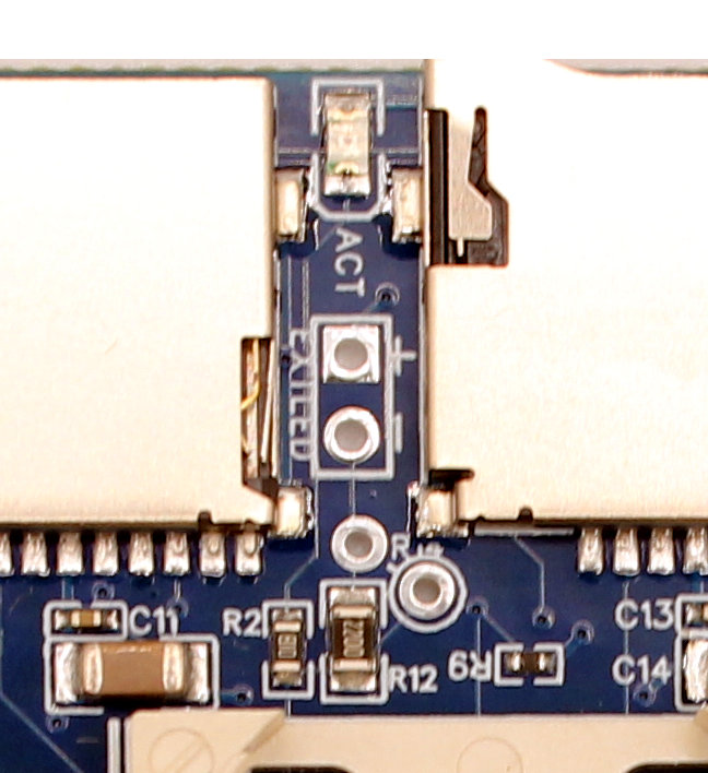
Earlier ACSI2STM versions included an onboard orange SMD activity LED. However, since it’s not visible once the device is mounted inside an Atari Mega case, revision 2.1 (April 2025) added a circuit to support an external LED.
Circuit Components
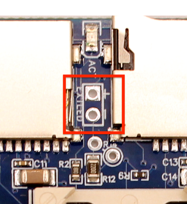
- EXTLED 1x2 Pin Header
A 2-pin header is provided on the PCB (below the onboard LED) labeledEXTLED. Polarity labels (+/-) are printed on the board.Note: This header is not pre-soldered. You must install it yourself.

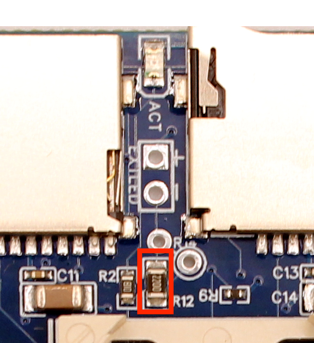
- SMD 220Ω Resistor
Soldered on the PCB by default, this resistor limits the current through the external LED.

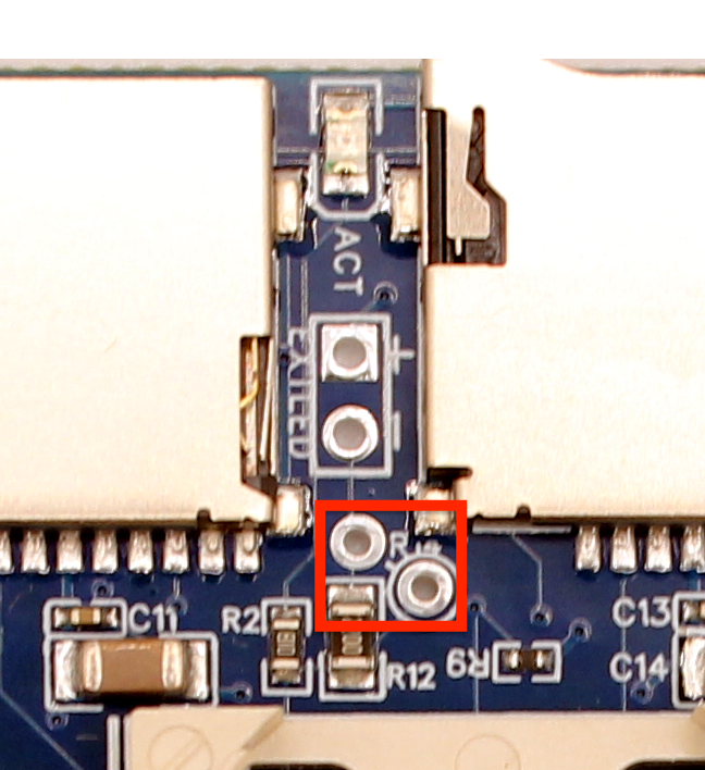
- Through-Hole Resistor Footprint
An alternative to the SMD resistor, this placeholder allows the user to fine-tune LED brightness with a custom resistor.Important: If you use the through-hole resistor, you should first remove the SMD resistor to avoid reducing total resistance too much.

By default, the circuit is compatible with the stock Mega STe front-panel HDD activity LED. However, LED brightness can vary depending on the LED’s forward voltage and current. In many cases, users may find the LED too dim and choose to replace the SMD resistor with a lower-value through-hole resistor (e.g., 220Ω or less).
🔌 Connecting the Mega STe Activity LED
Because the ACSI2STM cannot be placed directly inside the Mega STe case, you’ll typically use a riser board like this one or a custom version.
To connect the activity LED:
- Locate the front-panel HDD activity LED connector (a 2-wire cable inside the drive bay).
- Unplug it from the Atari motherboard.
- Connect it to the
EXTLEDheader on your ACSI2STM board.Polarity is critical
That’s it. If the LED brightness is not ideal, continue to the section on resistor customization.
🔌 Connecting a Custom LED on the Mega ST
Unlike the Mega STe, the Mega ST has no built-in HDD activity LED, so you’ll need to build a basic LED cable:
- LED — Choose a 3mm or 5mm LED with suitable forward voltage (~2.0V for red/green).
- Resistor — Use the SMD resistor on the board, or replace it with a through-hole resistor of your choice.
- Cable — A simple 2-wire cable with a 1x2 female connector (Dupont) is ideal.
Be sure to observe LED polarity: the longer leg is positive (+).
👉 You can place the LED anywhere you like — for example, drill a small hole in the front of the Mega ST case for a clean install.
🔧 Using a Custom Through-Hole Resistor
If the default 220Ω SMD resistor doesn’t provide the brightness you want, you can swap it for a through-hole resistor:
- Remove the SMD resistor using a soldering iron and tweezers.
- Install a through-hole resistor in the designated footprint.
Start with values like 220Ω for ~6mA, or 470Ω for ~3mA, depending on your LED specs and desired brightness.
⚠️ Important: Do not leave both resistors in place — using the SMD and through-hole resistor together will reduce total resistance too much and may damage the LED or overdraw GPIO current.